Harmonic Phenomena
- Excessive heating and failure of capacitors & capacitor fuses, Transformers, electric motors, fluorescent lighting ballasts, etc.
- Nuisance tripping of circuit breaker or blown fuses
- Presence of the third harmonic & multiples of the 3rd harmonic in neutral grounding systems may require the derating of neutral conductors
- Noise from harmonics that lead to erroneous operation of control system components
- Damage to sensitive electronic equipment
- Electronic communications interference
- Any device with non-linear operating characteristics can produce harmonics in your power system. If you are currently using equipment that can cause harmonics or have experienced harmonic related problems, capacitor reactor or filter bank equipment may be the solution. The following is a discussion of harmonics; the characteristics of the problem; and a discussion of our solution.
Origins of Harmonic Distortion
The ever increasing demand of industry and commerce for stability, adjustability and accuracy of control in electrical equipment led to the development of relatively low cost power diodes, thyristors, SCRs and other power semi-conductors. Now used widely in rectifier circuits for UPS systems, static converters and A.C. & D.C. motor control, these modern devices replace the mercury arc rectifiers of earlier years and create new and challenging conditions for the power engineer of today.
Although solid state devices, such as the thyristor, have brought significant improvements in control designs and efficiency, they have the disadvantage of producing harmonic currents. Harmonic currents can cause a disturbance on the supply network and adversely affect the operation of other electrical equipment including power factor correction capacitors. We are concentrating our discussions on harmonic current sources associated with solid state power electronics but there are actually many other sources of harmonic currents. These sources can be grouped into three main areas:
- Power electronic equipment: variable speed drives (AC VFD's, DC drives, PWM drives, etc.); UPS systems, rectifiers, switch mode power supplies, static converters, thyristor systems, diode bridges, SCR controlled induction furnaces and SCR controlled systems.
- Arcing equipment: Arc furnaces, welders, lighting (mercury vapor, fluorescent)
- Saturable devices: Transformers, motors, generators, etc. The harmonic amplitudes on these devices are usually insignificant compared to power electronic and arcing equipment, unless saturation occurs.
Waveform
Harmonics are sinusoidal waves that are integral multiples of the fundamental 60 Hz waveform (i.e., 1st harmonic = 60 Hz; 5th harmonic = 300 Hz). All complex waveforms can be resolved into a series of sinusoidal waves of various frequencies, therefore any complex waveform is the sum of a number of odd or even harmonics of lesser or greater value. Harmonics are continuous (steady-state) disturbances or distortions on the electrical network and are a completely different subject or problem from line spikes, surges, sags, impulses, etc., which are categorized as transient disturbances.
Transient problems are usually solved by installing suppression or isolation devices such as surge capacitors, isolation transformers or M.O.V.s. These devices will help solve the transient problems but will not affect the mitigation of low order harmonics or solve harmonic resonance problems.
Harmonic Content
Thyristor and SCR converters are usually referred to by the number of DC current pulses they produce each cycle. The most commonly used are 6 pulse and 12 pulse. There are many factors that can influence the harmonic content but typical harmonic currents, shown as a percentage of the fundamental current, are given in the below table. Other harmonics will always be present, to some degree, but for practical reasons they have been ignored.
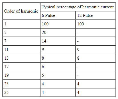
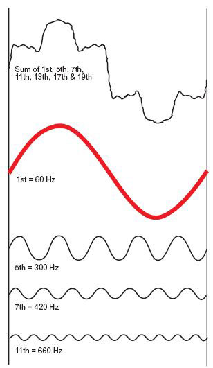
Figure 1.
Harmonic Overloading of Capacitors
The impedance of a circuit dictates the current flow in that circuit. As the supply impedance is generally considered to be inductive, the network impedance increases with frequency while the impedance of a capacitor decreases. This causes a greater proportion of the currents circulating at frequencies above the fundamental supply frequency to be absorbed by the capacitor, and all equipment associated with the capacitor.
In certain circumstances, harmonic currents can exceed the value of the fundamental (60 Hz) capacitor current. These harmonic problems can also cause an increased voltage across the dielectric of the capacitor which could exceed the maximum voltage rating of the capacitor, resulting in premature capacitor failure.
Harmonic Resonance
The circuit or selective resonant frequency is reached when the capacitor reactance and the supply reactance are equal. Whenever power factor correction capacitors are applied to a distribution network, which combines capacitance and inductance, there will always be a frequency at which the capacitors are in parallel resonance with the supply.
If this condition occurs on, or close to, one of the harmonics generated by solid state control equipment, then large harmonic currents can circulate between the supply network and the capacitor equipment. These currents are limited only by the damping resistance in the circuit. Such currents will add to the harmonic voltage disturbance in the network causing an increased voltage distortion. This results in a higher voltage across the capacitor and excessive current through all capacitor components. Resonance can occur on any frequency, but in general, the resonance we are concerned with is on, or close to, the 5th, 7th, 11th and 13th harmonics for 6 pulse systems. See Figure. 2.
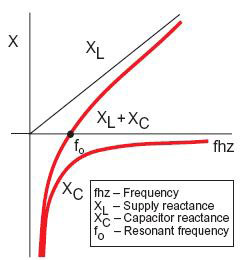
Figure 2.
Avoiding Resonance
There are a number of ways to avoid resonance when installing capacitors. In larger systems it may be possible to install them in a part of the system that will not result in a parallel resonance with the supply. Varying the kvar output rating of the capacitor bank will alter the resonant frequency. With capacitor switching there will be a different resonant frequency for each step. Changing the number of switching steps may avoid resonance at each step of switching. See Figure. 3.
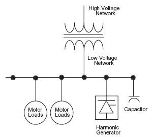
Figure 3.
Overcoming Resonance
If resonance cannot be avoided, an alternative solution is required. A reactor must be connected in series with each capacitor such that the capacitor/reactor combination is inductive at the critical frequencies but capacitive at the fundamental frequency. To achieve this, the capacitor and series connected reactor must have a tuning frequency below the lowest critical order of harmonic, which is usually the 5th. This means the tuning frequency is in the range of 175 Hz to 270 Hz, although the actual frequency will depend upon the magnitude and order of the harmonic currents present.
The addition of a reactor in the capacitor circuit increases the fundamental voltage across the capacitor. Therefore, care should be taken when adding reactors to existing capacitors. See Figure. 4.
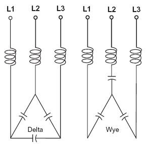
Detuned Capacitor/Reactor Systems Figure 4.
Reduction of Harmonic Distortion
Harmonic currents can be significantly reduced in an electrical system by using a harmonic filter. In its basic form, a filter consists of a capacitor connected in series with a reactor tuned to a specific harmonic frequency. In theory, the impedance of the filter is zero at the tuning frequency; therefore, the harmonic current is absorbed by the filter. This, together with the natural resistance of the circuit, means that only a small level of harmonic current will flow in the network.
Types of Filters
The effectiveness of any filter design depends on the reactive output of the filter, tuning accuracy and the impedance of the network at the point of connection. Harmonics below the filter tuning frequency will be amplified. The filter design is important to ensure that distortion is not amplified to unacceptable levels. Where there are several harmonics present, a filter may reduce some harmonics while increasing others. A filter for the 7th harmonic creates a parallel resonance in the vicinity of the 5th harmonic with magnification of the existing 5th harmonic; therefore, a 7th harmonic filter requires a 5th harmonic filter. See Figure. 5.
Consequently, it is often necessary to use a multiple filter design where each filter is tuned to a different frequency. Experience is extremely important in the design of such filters to ensure:
(a) the most efficient and cost effective solution is selected;
(b) no adverse interaction between the system and the filter.
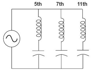
Shunt Filters Figure 5.
Load Alteration
Whenever load expansion is considered, the network is likely to change and existing filter equipment should be evaluated in conjunction with the new load condition. It is not recommended to have two or more filters tuned to the same frequency connected on the same distribution system. Slight tuning differences may cause one filter to take a much larger share of the harmonic distortion. Or, it may cause amplification of the harmonic order which the equipment has been designed to reduce. When there is a need to vary the power factor correction component of a harmonic filter, careful consideration of all load parameters is necessary.
Harmonic Analysis
The first step in solving harmonic related problems is to perform an analysis to determine the specific needs of your electrical distribution system. To determine capacitor and filter requirements, it is necessary to establish the impedance of the supply network and the value of each harmonic current. Capacitor, reactor and filter bank equipment are then specified under very detailed and stringent computer analysis to meet your needs.
Your ABB Solution to Harmonics
ABB is the world's largest manufacturer of dry type low voltage capacitors! ABB Control Inc. utilizes this experience in recommending three options to solve the problems associated with applying capacitors to systems having harmonic distortion:
- Apply the correct amount of capacitance (kvar) to the network to avoid resonance with the source. This may be difficult, especially in automatic systems as the capacitance is always changing. This solution usually means connecting less capacitance to the system than is actually needed for optimum power factor correction.
- Install reactors in series with capacitors to lower the resonance below critical order harmonics; i.e., 5th, 7th, 11th & 13th. This design tunes the resonant frequency of the system well below the critical harmonic and is called an anti-resonance bank. This solution allows the capacitors to operate in a harmonic environment.
- Filters are recommended if a problem exists with harmonic distortion before the application of power factor correction, or if the harmonic distortion is above the limits recommended in IEEE 519, "Guide for Harmonic Control and Reactive Compensation of Static Power Converters". (The recommended limits for voltage distortion in IEEE 519 are presently 5% for general applications.) Tuned filters sized to reduce the harmonic distortion at critical frequencies have the benefits of correcting the power factor and improving the network power quality.
With our knowledge of harmonics, ABB provides a complete range of products from individual capacitors, fixed banks and automatic banks, to power filter systems. All these products utilize dry type low voltage ABB power factor correction capacitor elements which are self-healing for internal faults.
To maintain stringent quality control standards, most control components found in automatic and anti-resonance filter bank products are also ABB products. These products include contactors, circuit breakers, control relays, disconnect switches, power factor relays and pushbutton devices.
ABB Capacitor Features & Services
Every ABB Control low voltage capacitor product incorporates our unique dry type design. Therefore, environmental and personnel concerns associated with leakage or flammability of conventional oil-filled units are eliminated. Other features include:
- Patented Sequential Protection System includes dry, self-healing design; internally protected elements; and dry, non-flammable vermiculite filler
- Individual units, fixed and automatic capacitor bank designs, 208-600V
- Automatic and fixed tuned or anti-resonance capacitor banks
- Power factor and harmonic studies
- UL and CSA