Contrinex Glossary of Terms
Contrinex 12th Dec 2022
Contrinex Glossary of Terms
ADJUSTMENT (POTENTIOMETER)
The sensitivity is adjusted by means of the built-in single or multi-turn potentiometer (if provided). Turning it clockwise increases the sensitivity. Multi-turn potentiometers cannot be turned over their end position (no stops).
THROUGH-BEAM SENSORS / REFLEX SENSORS
The potentiometer is normally set to the maximum sensitivity (turned clockwise). This provides the maximum system reserve (excess-gain) signal.
DIFFUSE SENSORS
Set the sensitivity so that the target is reliably detected; for reliable operation, the green LED should light up, or the yellow LED should not flash (series 1040/1050/0507). On removing the object, if the output remains ON (detection of the background), the sensitivity must be reduced slightly.
DIFFUSE SENSORS WITH BACKGROUND SUPPRESSION
The setup must ensure that the target is clearly identified, and any background excluded. The target should first be positioned at the maximum foreseen distance from the emitter, and the potentiometer adjusted so that the output just switches. The target is then removed and the potentiometer adjusted so that the background just causes the output to switch. Finally, the potentiometer is set to half way between the two previous readings. Where there is no background, the potentiometer should be set to the maximum distance.
ALIGNMENT
THROUGH-BEAM SENSORS
First place the receiver and fix it in its final position. Then align the emitter accurately onto the receiver.
REFLEX SENSORS
First place the reflector as required and fix it firmly in position. Fit the reflex sensor with the optical axis aligned on the reflector so that it switches reliably. Test with target. Reduce sensitivity if necessary.
DIFFUSE SENSORS
Align the unit’s optical axis with the target so that switching occurs reliably. Check that enough system reserves (excess gain) are available, i.e. the green LED must light up (series 1120, 1180, 1180W, 3030, 3031, 3060, 4040, 4050 and C23). Finally, fix the device firmly.
DIFFUSE SENSORS WITH BACKGROUND SUPPRESSION
Line up the beam on the center of the target, before fixing the device firmly.
AMBIENT LIGHT LIMIT
Ambient light is that which is produced by external light sources. The illumination intensity is measured on the light incidence surface. The sensors are basically insensi- tive to ambient light due to the use of modulated light. There is nevertheless an upper limit for the intensity of any external light and this is referred to as the ambient light limit. It is given for sunlight (unmodulated light) and halogen lamps (light modulated at twice the mains frequency). Reliable operation of the units is no longer possible at light intensities above the relevant ambient light limit.
AMBIENT TEMPERATURE
The specified ambient temperature range must not be exceeded in order to avoid damaging the sensor and rendering its performance unreliable.
ANALOG OUTPUT
Devices with analog output deliver an analog output signal approximately proportional to the target distance. For most models, voltage and current outputs are available simultaneously.
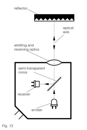
AUTOCOLLIMATION
Photoelectric sensors using the autocol- limation principle are characterized by the fact that the optical axes of the emitting and receiving channels are identical. This is possible with light from one of the channels being deflected by means of a semi-transparent mirror (Fig. 13). This principle completely eliminates the interfering blind zone often found in the proximity of the sensor, which is of special advantage when using reflex sensors.
BACKGROUND SUPPRESSION
The light pulse from the emitting diode leaves the optical system as a focused, almost parallel, light beam. On meeting an object in its path, part of the beam is diffusely reflected, and in turn, part of this reflected light falls on the PSD (Position- Sensitive Device) housed in the same sensor (Fig. 14).
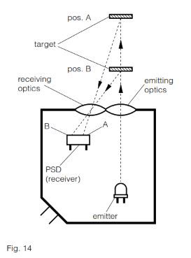
Depending on the distance of the target from the device, the light falls on a particu- lar spot of the PSD, and a corresponding reception signal is emitted, indicating that an object is present at a certain distance from the device. The analyzing circuit compares the signal received with the preset operating distance (adjusted by means of the built-in potentiometer), and, if the distance of the object is less than, or equal to, the preset operating distance, the output is switched. Contrary to an energetic diffuse sensor, the operating distance depends only to a very small extent on the target’s size or color, or on the nature of its surface. The object can therefore be easily discerned, even against a light background.
CAPACITANCE
The maximum switchable capacitance is the greatest permissible total capacitance at the device’s output so that reliable switching is still guaranteed. Contributing to this total capacitance in particular are the lead capacitance (approx. 100 ... 200 pF per m) and the load’s input capacitance. The value is given in the individual data sheets. These can be ordered from our sales offices.
CE MARK
All sensors in this catalog meet the requirements of European standards EN 60947-1 and EN 60947-5-2, and therefore correspond to EMC directive 2004/108/EC, as well as low-voltage directive 2006/95/EC. Consequently, they are labeled with the CE mark.
However, this mark is neither a quality seal, nor an official test label certified by any authority. By applying the CE mark, the manufacturer confirms (under his own responsibility) that the protective requirements for the product meet the applicable EU directives, and consequently that the corresponding EU standards have been complied with. The CE mark enables the free importation of goods into the EU, as well as their free circulation within the EU.
CHANGEOVER
Devices with changeover outputs provide one output for the light-ON or NO signal, and another for the dark-ON or NC signal. Both functions are available simultaneously for maximum connection flexibility to the control unit. Moreover, logical connections may be implemented without using series connection. Connecting both outputs to the control unit allows additional security monitoring.
CLASSICS FAMILY
The Classics family (600 series) is one of three inductive sensing technologies offered by Contrinex. Classics family sensors rely on conventional inductive oscillator and coil technology (see page 20).
Sensors are sized from Ø 3 up to M30 and C44 (40 mm x 40 mm). PNP, NPN and 2-wire AC/DC output configurations are available, combined with sensing distances between 0.6 mm and 40 mm.
The Classics technology family includes devices from the following ranges: Basic, Miniature, 2-wire, Extra pressure, Extra temperature, High temperature and Washdown.
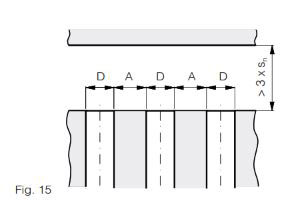
CLEARANCE
Inductive sensors must not mutually influence each other. For this reason, a minimum distance A between devices of diameter D must be observed (Fig. 15).
EXTRA DISTANCE (SERIES 500, 520*)
| Size D | (quasi)-embed. A (mm) | non-emb. A (mm) |
|---|---|---|
| Ø 4 | 6 (embeddable) | --- |
| M5 | 5 (embeddable) | --- |
| Ø 6.5 | 9.5 | --- |
| M8 | 8/*16 | 20 |
| C8 | 8 | --- |
| M12 | 18/*34 | 30 |
| M18 | 26 | 60 |
| M30 | 50 | 120 |
CLASSICS (SERIES 600, 620*)
| Size D | embeddable A (mm) | non-emb. A (mm) |
|---|---|---|
| Ø 3 | 0/*2 | --- |
| M4 | 0/*1 | --- |
| Ø 4 | 0/*1 | --- |
| M5 | 0/*1 | --- |
| C5 | 0/*1 | --- |
| Ø 6.5 | 3/*3.5 | ---/*15.5 |
| M8 | 2/*4 | 10/*14 |
| C8 | 2/*2 | --- |
| M12 | 4/*12 | 28/*33 |
| M18 | 7/*22 | 32 |
| M30 | 10 | 50 |
| C44 | 35 | 120 |
FULL INOX (SERIES 700)
| Size D | embeddable A (mm) | non-emb. A (mm) |
|---|---|---|
| M8 | 14 | 52 |
| M12 | 38 | 108 |
| M18 | 42 | 182 |
| M30 | 80 | 270 |
Photoelectric sensors must not mutually influence each other. For this reason, a minimum distance "a" between them has to be respected, which depends strongly on the model used and the actual sensitivity setting. The following values should therefore be considered as rough guidelines only. The values given are for maximum sensitivity.
DIFFUSE SENSORS WITH BACKGROUND SUPPRESSION
| Series | distance a (mm) |
|---|---|
| Series 1180/1180W | 50 |
| Series 3130 | 50 |
| Series 3131 | 50 |
| Series 4050 | 100 |
DIFFUSE SENSORS (FIG. 16)
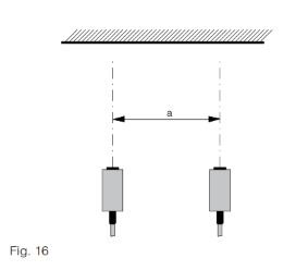
| Series | distance a (mm) |
|---|---|
| Series 1040/50 | 50 |
| Series 1040/50...505 | 15 |
| Series 1040/50...506 | 30 |
| Series 1120 | 150 |
| Series 1180/1180W | 500 |
| Series 3030 | 500 |
| Series 3031 | 250 |
| Series 4050 | 150 |
REFLEX SENSORS (FIG. 17)
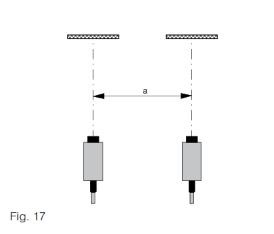
| Series | distance a (mm) |
|---|---|
| Series 1120 | 150 |
| Series 1180/1180W | 250 |
| Series 3030 | 500 |
| Series 3031 | 250 |
| Series 4050 | 200 |
THROUGH-BEAM SENSORS (FIG. 18)
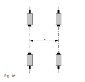
| Series | distance a (mm) |
|---|---|
| Series 1040/50 | 50 |
| Series 1120 | 150 |
| Series 1180/1180W | 250 |
| Series 3030 | 500 |
| Series 3031 | 250 |
| Series 4050 | 500 |
FIBER-OPTIC AMPLIFIERS
The value "a" depends strongly on the specific type of fiber used. General recom- mendations are therefore not possible.
CONDET TECHNOLOGY
An innovative technology for producing inductive sensors. Contrary to conventional technology, in which a high-frequency magnetic field is generated in front of the sensing face, here the coil is triggered by an alternating polarity pulsed current. This technology is used in the Full Inox family (700 series) (see also page 21).
It permits:
− generally long operating distances
− long operating distances also on non- ferrous metals, such as aluminum, brass, copper, etc.
− one-piece stainless steel housing
(sensing face included)
− long operating distances also on non- ferrous metals, such as aluminum, brass, copper, etc.
− one-piece stainless steel housing
(sensing face included)
CONDIST TECHNOLOGY
Developed by Contrinex, this innovative technology makes use of a high-perfor- mance oscillator for inductive sensors. Operating distances from 2.2 to 4 times the standard values are possible thanks to excellent temperature and voltage stabil- ity. Devices of the Extra distance family (500 and 520 series) work with such an oscillator (see also page 20).
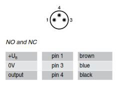
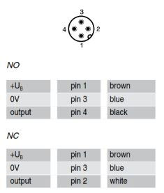
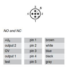
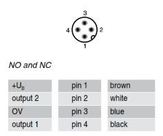
CONNECTORS
PIN ASSIGNMENT SIZE S8:
Detailed data sheets for these products can be found on the Contrinex website:
PIN ASSIGNMENT SIZE S12:
PIN ASSIGNMENT SIZE 1/2":
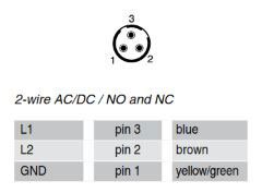
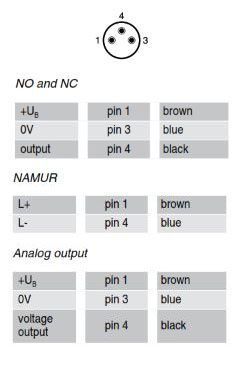
PIN ASSIGNMENT SIZE S8 3 POLE:
PIN ASSIGNMENT SIZE S12 3 POLE:
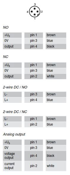
PIN ASSIGNMENT SIZE S12 5 POLE:
PIN ASSIGNMENT S8 4 POLE:
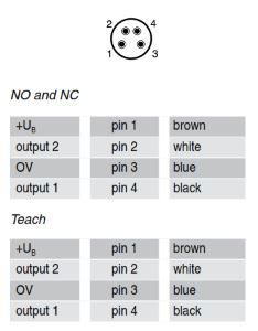
PIN ASSIGNMENT S12 4 POLE:
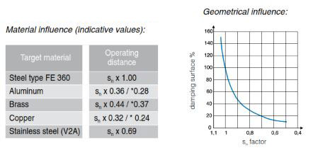
CORRECTION FACTORS
The specified operating distance s of inductive sensors refers to exactly defined measuring conditions (see OPERATING DISTANCE).
Other arrangements generally result in a reduction of the operating distance. The fol- lowing data are to be considered as guidelines only; according to size and version, there can be wide variations. Exact values are given in the individual data sheets. These can be ordered directly from our sales offices.
CLASSICS (SERIES 600 / 620)
When using foils, an increase in the usable operating distance can be expected.
EXTRA DISTANCE (SERIES 500 / 520*)
When using foils, an increase in the usable operating distance can be expected.
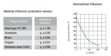
FULL INOX (SERIES 700)
Material influence (indicative values):
| Target material | Operating distance |
|---|---|
| Steel type FE 360 | Sn x 1.0 |
| Aluminum | Sn x 1.0 |
| Brass | Sn x 1.3 |
| Copper | Sn x 0.8 |
| Stainless Steel (1 mm thick) | Sn x 0.5 |
| Stainless Steel (2 mm thick) | Sn x 0.9 |
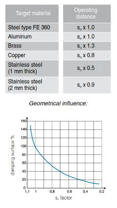
When using foils, a decrease in the usable operating distance can be expected.
Test card (Kodak paper, white) 100%
Paper, white 80%
PVC, gray 57%
Newspaper, printed 60%
Wood, lightly colored 73%
Cork 65%
Plastic, white 70%
Plastic, black 22%
Neoprene, black 20%
Automobile tires 15%
Aluminum sheet, untreated 200%
Aluminum sheet, black anodized 150%
Aluminum sheet, matt (brushed finish) 120%
Stainless steel, polished 230%
The specified sensing ranges of energetic diffuse sensors are achieved using standard matt white paper of the specified dimensions as the target surface. For other target surface materials, the correction factors listed here apply (these are guideline values only).
DARK-ON
The "dark-ON" function means that the relevant output is switched (carrying current) when no light is reaching the receiver.
DEGREES of PROTECTION
The IP degrees of protection are defined in DIN 40050 / IEC 60529. The meaning of the first numeral is:
6 The housing provides complete protection against contact with electrically con- ducting or moving parts, and full protection against dust penetration.
and the second numeral:
4 Protection against water splashes: water splashed against the housing from any direction must have no harmful effect. Test conditions: spraying with oscillating tube or spray nozzle; water pressure 1 bar; delivery rate 10 l/min ± 5%; duration 5 minutes.
5 Protection against water jets: water projected by a nozzle from any direction under specified conditions must have no harmful effect. Test conditions: nozzle with 6.3 mm diameter; delivery rate 12.5 l/min ± 5%; distance 3 m; duration 3 minutes.
7 Protection against water when device is immersed in water under specified pres- sure and time conditions. Water must not penetrate in damaging quantities. Test conditions: immersion depth in water 1 m; duration 30 minutes.
8 Protection against water when device is immersed in water indefinitely under specified pressure conditions. Water must not penetrate in damaging quantities. Test conditions used by Contrinex: immersion depth in water 5 m; duration ≥ 1 month.
9K Protection against water which, if directed against the housing from any direction and under considerably increased pressure, must have no harmful effect. Test conditions: sensor mounted on table turning at 5 ± 1 rpm; spraying with flat nozzle; delivery rate 14 - 16 l/min; distance 100 - 150 mm; angles 0°, 30°, 60° and 90°; temperature 80 ± 5°C (176 ± 41of); pressure 8,000 - 10,000 kPa (80 - 100 bar / 1160.8 - 1451 psi); duration 30 sec per position.
Devices with degree of protection IP 67 are thus not intended for prolonged operation in water, or in prolonged humid conditions. Tolerance to liquids other than water must be examined from case to case.
EMBEDDABLE MOUNTING
See MOUNTING.
EMC
The EMC (Electromagnetic Compatibility) resistance of the devices satisfies the highest demands. For exact values, please refer to the data sheets. All devices comply with the EU directive no. 2004/108/EC. In addition, they undergo severe field testing.
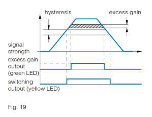
EXCESS-GAIN INDICATION (SYSTEM RESERVE INDICATION)
The excess-gain indication circuit detects the excess radiation power which falls on the light incidence surface and is proc- essed by the light receiver. The excess gain can decrease in time due to dirt, a change in the target’s reflection factor, and aging of the emitter diode, so that reliable operation can no longer be guaranteed. Some devices are therefore equipped with a second LED (green), which lights up when less than approximately 80% of the available operating distance is used. Models with an excess-gain output make the excess-gain signal available to the user for further processing. Thus, operating condi- tions which are no longer reliable can be recognized in time.
EXTRA DISTANCE FAMILY
The Extra Distance family (series 500/520) is one of three inductive sensing tech- nologies offered by Contrinex. Extra Distance family sensors rely on conventional inductive oscillator and coil technology, but with a completely different signal evaluation circuit for better stability and therefore long operating distances. The most important contribution to this comes from the Contrinex Condist oscillator (see pages 20-21). Sensors are sized from Ø 4 to M30, with long operating distances up to 40 mm. The Extra Distance technology family includes devices from the Basic, Miniature, Extra pressure, High pressure and Analog output ranges.
FULL INOX FAMILY
The Full Inox family (series 700) is one of three inductive sensing technologies of- fered by Contrinex. Full Inox family sensors rely on Contrinex’s patented Condet technology (see page 21).
Full Inox sensors have a one-piece, stainless steel housing and are exceptionally robust and chemically resistant. They are not only the most durable inductive sensors on the market, but also offer long operating distances on any conductive metal.
Sensors are sized from Ø 4 to M30 and cuboid variant of 20 x 32 x 8 mm, with long operating distances up to 40 mm and protection class IP 67 and IP 69K.
The Full Inox technology family includes devices from the Basic, Miniature, Extreme, High pressure, Washdown, Weld-immune, Chip-immune, Double-sheet and Maritime ranges.
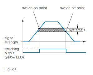
HYSTERESIS
Hysteresis (differential travel) causes a defined switching behavior of the device (Fig. 20). The sensing range always refers to the switch-on point. Distance hysteresis is only useful for the diffuse sensor model and its related fiber version.
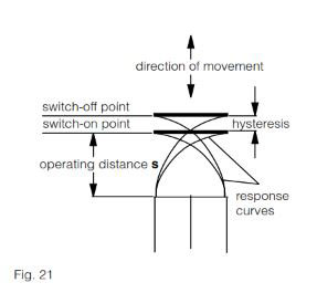
Hysteresis (differential travel) causes a defined switching behavior of the device (Fig. 21). The operating distance always refers to the switch-on point. Namur devices and those with analog output have continuous transmission behavior, i.e. there is no hysteresis.
INDUCTION PROTECTION
When inductive loads are switched off, the output voltage, without a protective circuit, would increase to a high value, which could destroy the output transistor. Contrinex sensors therefore contain a Zener diode at the output to limit the switch-off voltage to a safe value (3-wire types). When connecting an inductive load with a current >100 mA and simultaneously a switching frequency >10 Hz, the mounting of a free-wheeling diode directly to the load is recommended (due to the leakage power in the built-in Zener diode).
INSTALLATION
Photoelectric sensors can be easily and reliably installed in any position, using the mounting accessories supplied with most devices. The installation position should preferably protect the units against dirt and other contamination.
For inductive sensors, see MOUNTING.
INSULATION VOLTAGE
The devices in this catalog are designed for an insulation voltage (between connect- ing leads and housing) of 75 VDC / 50 VAC (for supply voltages up to 75 VDC / 50 VAC) or 300 VDC / 250 VAC (for supply voltages between 75 VDC / 50 VAC and 300 VDC / 250 VAC).
IP 64 / IP 65 / IP 67 / IP 68 / IP 69K
Refer to DEGREES of PROTECTION.
IR LIGHT
IR is the abbreviation of "Infra-Red". This refers to any electromagnetic radiation with a wavelength exceeding that of normal visible light, which is approx. 380 to 780 nm. Wavelengths of approx. 780 to 1500 nm are typically used. IR light cannot be used with synthetic fibers, due to high at- tenuation. Instead, visible red light is used. As the usual polarization filters cannot be used in the IR range, visible red light is also used for reflex sensors.
LEAD LENGTHS
For the sensor, long leads mean:
− a capacitive load at the output (see CAPACITANCE)
− increased influence of interference signals
− increased influence of interference signals
Even under favorable conditions, lead lengths should not exceed 300 m.
LEADS
The standard built-in leads are not suit- able for repeated bending stresses. In such cases, high-flexibility PUR cables (special executions) or connectors with corresponding connecting cables (see pages 441-449) must be used.
LEAKAGE CURRENT
Leakage current is the current that flows through the output transistor and thereby through the load when the output is OFF (to be taken into account particularly where switches are connected in parallel).
LED
Most of the inductive devices in this catalog are equipped with a built-in yellow light- emitting diode (LED). It indicates the switching state: output activated = yellow LED on.
All photoelectric sensors have one or two Light Emitting Diodes (LEDs) built in. The yellow LED lights up when the output is switched (for switches with 2 outputs: the light-ON output). During a short-circuit or overload, the yellow LED does not operate. The green LED (if provided) lights up when enough system reserves (excess gain) for reliable operation are available, i.e. when an object is present in the reliable sensing area (diffuse sensors), or when enough light from the uninterrupted beam reaches the receiver (reflex and through-beam sensors).
LIGHT-ON
Light-ON means that the relevant output is switched (carrying current) when light is reaching the receiver.
LOAD RESISTANCE
From the selected supply voltage UB and the specified maximum output current of the senso
12th Dec 2022
Recent Posts
-
Absolute Encoders — Facts and Misconceptions
Ray Marquiss 11th Sep 2023There are two parts of motion control systems often overlooked or misunderstood; encoders for … -
What is a Compound Pressure Gauge and When to Use One?
Valin 12th Dec 2022What is a Compound Pressure Gauge and When to Use One? I just got off the phone with a … -
What is an Encoder?
Encoder Products Company 12th Dec 2022If you search the definition of an encoder, you will get a vast and confusing array of responses. …