Inductive Proximity Switches with Large Operating Ranges
Contrinex 12th Dec 2022
Inductive Proximity Switches with Large Operating Ranges: The Technology, Characteristics and Application Advantages
Development History of lnductive Proximity Switches
The inductive proximity switches' time came at the beginning of the 1960's. Due to their reliability, high quality to price ratio and ease of installation they have conquered a wide range of applications. Despite many technical improvements, one of the substantial and long standing drawbacks of these devices was the poor ratio of construction size to switching distance. In 1982, however, a two to threefold increase in the switching distance was achieved using a new oscillator concept for devices using the inductive principle of operation. Since then they have proved themselves effective in many applications. In the following paragraphs we will take a closer look at the essential characteristics and applications of these devices.
Technology
To attain higher switching distances, the Condist oscillator was developed. Inductive proximity switches fitted with this oscillator work on the same physical principles as customary market designs: a high frequency electromagnetic field is induced in the region over the sensor surface by a resonance coil. Conductive materials within the area of this magnetic field induce an eddy current loss which consequently changes the operation of the oscillator. The subsequent evaluation electronics measures and calculates this change. Since these fundamental operating principles have not changed the application characteristics of the Condist oscillator also remain unchanged. The only real distinction is the enlargement of the switching distance, which is made possible by a much better temperature stability of the oscillators.
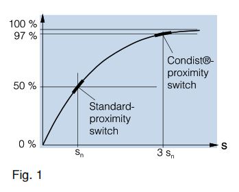
Fig. 1 shows the correlation between the resonance attenuation and the measuring plate distance from the resonance coil. Devices fitted with the Condist oscillator show an identical relationship to standard oscillators, except that the switching point is moved to the right in the direction of larger switching distances. Due to the unique stability of these oscillators, this is possible without any otherwise expected degradation of the other proximity switch characteristics.
Characteristics
The following information shows the important differences for the user between standard proximity switches and those fitted with a Condist oscillator.
Table 1: Switching Distance
| Size | Condist | Standard |
|---|---|---|
| M8 flush mounted | 3 mm | 1 mm |
| M8 not flush mounted | 6 mm | 2 mm |
| M12 flush mounted | 6 mm | 2 mm |
| M12 not flush mounted | 10 mm | 4 mm |
| M18 flush mounted | 12 mm | 5 mm |
| M18 not flush mounted | 20 mm | 8 mm |
| M30 flush mounted | 22 mm | 10 mm |
| M30 not flush mounted | 40 mm | 15 mm |
Table 2: Switching Frequency
| Size | Condist | Standard |
|---|---|---|
| M8 flush mounted | 1000 Hz | 1000 Hz |
| M8 not flush mounted | 500 Hz | 500 Hz |
| M12 flush mounted | 800 Hz | 800 Hz |
| M12 not flush mounted | 400 Hz | 400 Hz |
| M18 flush mounted | 200 Hz | 500 Hz |
| M18 not flush mounted | 200 Hz | 200 Hz |
| M30 flush mounted | 150 Hz | 300 Hz |
| M30 not flush mounted | 100 Hz | 100 Hz |
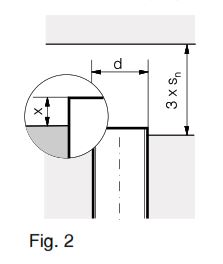
'Flush' mounted devices with large switching distances should not, in fact, be absolutely flush (quasi-flush). That is, in unfavourable cases, the switch should project out by a distance X (as shown in fig. 2). The distance 'X' is dependent on the switch size and is variable within the range of 0.05 to
0.2 times the casing diameter.
0.2 times the casing diameter.
All of the remaining characteristics also correspond in principle, but in particular:
- Operating voltage and output current
- Current consumption
- Temperature range
- Protection circuit, EMC characteristics
- Resistance to the environment
Most Useful Applications
The following useful examples have been taken from concrete practical instances, in which the greater switching distance of devices fitted with Condist oscillators is shown to best advantage.
Case 1: Requirements for a switching distance of ≥ 10 mm and an outside diameter of ≤ 20 mm
Further stipulations: quasi-flush and normally dimensioned installation. The normal device needed for the measurement distance of sn 10 mm requires a switch size of M30, which is far too large. The next smallest size of standard devices is an M18 which has an insufficient switching distance of 5 mm. The device with the largest switching distance within the size M18 is sn = 12 mm. The requirement is therefore, easily fulfilled.
Case 2: Dependence of switching distances on gearwheel teeth size
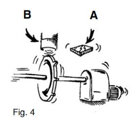
The effective working surface, B (see fig. 4) is much smaller than that of a standard measuring plate, A (as specified in any catalogue). However, with a much less effective measuring surface, the switching distance becomes very much reduced. For example in fig. 4, a distance of 2 mm (catalogue value) might be reduced to, say, 0.5 mm (dependent on the cross-sectional size of the gearwheel teeth). The resulting switching distance in these cases is often too small and in the practical installation there is always the danger of mechanical damage to the switching device due to contact with the gearwheel teeth - especially where a lot of adjustment work is required. The installation of a device with a large switching distance gives, in this example, a switching distance of 1.5 mm, which solves the problem.
Case 3: Detection of electrical cables
The detection of cables with standard inductive devices is, as a rule, not possible. Firstly, the cable isolation prevents the are very good. A non-flush mounted, installable M30 device is recommended here.
Case 4: Adjustment of proximity switches on running machinery
Often the fine adjustment of the switches cannot be accomplished statically (for example with a moving object) and must be achieved while the machine is at operating speed. A small error from the personnel installing the device for the first time can lead to damage to the equipment and in addition can also lead to accidents to personnel. Here, the installation of devices with a large switching distance is an obvious advantage - and the risks of a collision with a moving objects are minimized.
Case 5: Field maintenance
While it is good practice to use trained production personnel for the installation and adjustment of switches, maintenance at the user' facility should not require such high standards. Defective standard proximity switches can be replaced using unskilled personnel since the need for high precision installation is not now so important.
Case 6: Replacement of original proximity switches
During the initial setting up of an installation, the proximity switches chosen often only just fulfill the requirements of the situation - usually due to cost considerations - which can increase the risk of mechanical damage to the equipment. However, replacement of initially installed switches by switches with a large switching distance, in particular in well-known trouble areas, can improve this situation and reduce costly machine downtime.
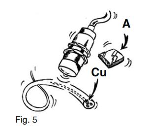
Case 7: Detection of thin wires
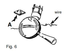
The use of inductive proximity switches for the detection of thin wires is in general difficult due to the small effective surface, and is in reality often impossible. Here, photoelectric devices are much better (laser photoelectric barrier devices or solutions with optical fibers). This solution does involve increased costs, and moreover, installation in polluted environments requires special precautions and skill. ln many cases proximity switches with a large switching distance offer an interesting alternative. Non-flush, M30 sized devices are the best suited. Copper wires of diameter 0.5 mm can be, for example, recognized at a distance of 6 mm, whereas with standard devices this recognition is impossible.
Case 8: Application of protection covers
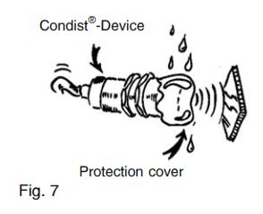
Additional protection for these devices, such as covers and top caps, is possible for use in hostile environments or as protection against mechanical damage. However, an undesirable reduction in the useable switching distance will be incurred by using this protection. Devices with a large switching distance in this case still maintain an acceptable result.
Case 9: Sheet metal processing
Processed and unprocessed sheet metals require larger mechanical tolerances than other metal parts. This leads to, for example, the problem of presence detection. lf the switch is installed near to the moving part of sheet metal for reliable switching, the danger always exists of mechanical damage to the switch. lf it is installed at a safe distance, the recognition is unreliable which impedes the production run or procedure. lnductive devices with large switching distances by their very nature provide a great advantage.
Case 10: Conveyor-belt systems
On one hand, conveyor-belt systems are characterized by the large number of switches required for the control system. On the other hand, the installation of the switches is problematic due to the fact that the chains, conveyor belts and accessories have a considerable amount of mechanical play. Inductive proximity switches using standard switching distances are often unsuitable in these circumstances since the required switching distances demand large diameter proximity switches, which is often in conflict with the available space. Photoelectric devices would do the job, but they are not liked by the operators because there is always a dirty, polluted environment around the conveyors requiring periodic cleaning. Inductive devices with a large switching distance enable an easy, cost-effective and sure solution.
12th Dec 2022