Description of AC Motor Operation
Lenze Americas 12th Dec 2022
Description of AC Motor Operation
Three phase AC motors are comprised of two major components, the stator and the rotor. The stator is a set of three electrical windings held stationary in the motor housing. The rotor is a metal cylinder, fixed to the motor drive shaft, which rotates within the stator. The arrangement of the stator coils and the presence of three phase AC voltage give rise to a rotating magnetic field which drives the rotor. The speed at which the magnetic field rotates is known as the synchronous speed of the motor. Synchronous speed is a function of the frequency at which the voltage is alternating and the number of poles in the stator windings.
The following equation gives the relation between synchronous speed, frequency, and the number of poles:
Ss = 120 f/p
Where: Ss = Synchronous speed (rpm)
f = frequency (Hz)
p = number of poles
In three phase induction motors the actual shaft speed differs from the synchronous speed as load is applied. This difference is known as “slip”. Slip is commonly expressed as a percentage of synchronous speed. A typical value is three percent at full load.
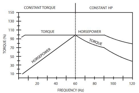
The strength of the magnetic field in the gap between the rotor and stator is proportional to the amplitude of the voltage at a given frequency. The output torque capability of the motor is, therefore, a function of the applied voltage amplitude at a given frequency. When operated below base (rated) speed, AC motors run in the range of "constant torque". Constant torque output is obtained by maintaining a constant ratio between voltage amplitude ( Volts) and frequency (Hertz). For 60 Hz motors rated at 230, 460, and 575 VAC, common values for this V/Hz ratio are 3.83, 7.66, and 9.58 respectively. Operating with these V/Hz ratios generally yields optimum torque capability. Operating at lower ratio values results in lower torque and power capability. Operating at higher ratio values will cause the motor to overheat. Most standard motors are capable of providing full torque output from 3 to 60 Hz. However, at lower speeds, where motor cooling fans become less effective, supplemental cooling may be needed to operate at full torque output continuously.
If the frequency applied to the motor is increased while the voltage remains constant, torque capability will decrease as speed increases. This will cause the horsepower capability of the motor to remain approximately constant. Motors run in this mode when operated above base speed, where drive output voltage is limited by the input line voltage. This operating range is known as the “constant horsepower” range. The typical maximum range for constant horsepower is about 2.3 to 1 (60 to 140 Hz). The diagram below depicts the characteristics of a typical AC induction motor with a 60 Hz base speed.
WARNING! Consult motor manufacturer or Lenze motor distributors like Valin before operating motor and/or driven equipment above base speed.
Variable Torque vs. Constant Torque
Variable frequency drives, and the loads they are applied to, can generally be divided into two groups: constant torque and variable torque. Constant torque loads include: vibrating conveyors, punch presses, rock crushers, machine tools, and just about every other application that is not considered variable torque. Variable torque loads include centrifugal pumps and fans, which make up the majority of HVAC applications.
Variable torque loads are governed by the affinity laws, which define the relationships between speed, flow, torque and horsepower. The diagram below illustrates these relationships:
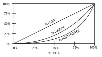
"Variable torque" refers to the fact that the torque required varies with the square of the speed. Also, the horsepower required varies with the cube of the speed, resulting in a large reduction in horsepower for even a small reduction in speed. It is easily seen that substantial energy savings can be achieved by reducing the speed of a fan or pump. For example, reducing the speed to 50% results in a 50 HP motor having to produce only 12.5% of rated horsepower, or 6.25 HP. Variable torque drives usually have a low overload capacity (110% - 120% for 60 seconds), because variable torque applications rarely experience overload conditions. To optimize efficiency and energy savings, variable torque drives are usually programmed to follow a variable V/Hz ratio.
The term "constant torque" is not entirely accurate in terms of the actual torque required for an application. Many constant torque applications have reciprocating loads, such as vibrating conveyors and punch presses, where the rotational motion of the motor is being converted to a linear motion. In such cases, the torque required can vary greatly at different points in the cycle. For constant torque loads, this fluctuation in torque is not a direct function of speed, as it is with a variable torque load. As a result, constant torque drives typically have a high overload rating (150% for 60 seconds) in order to handle the higher peak torque demands. To achieve maximum torque, constant torque drives follow a constant V/Hz ratio.
Both MC Series product lines (MC1000 and MC3000) have full overload capacity (150% for 60 seconds, 180% for 30 seconds), so that either one can be used for either type of application. The V/Hz ratio can also be changed to optimize performance for either type of application.
Drive Function Description
The MC Series is a 16 bit microprocessor based, keypad programmable, variable speed AC motor drive. There are four major sections: an input diode bridge and filter, a power board, a control board, and an output intelligent power module.
Drive Operation
Incoming AC line voltage is converted to a pulsating DC voltage by the input diode bridge. The DC voltage is supplied to the bus filter capacitors through a charge circuit which limits inrush current to the capacitors during power-up. The pulsating DC voltage is filtered by the bus capacitors which reduces the ripple level. The filtered DC voltage enters the inverter section of the drive, composed of six output intelligent insulated gate bi-polar transistors (IGBTs) which make up the three output legs of the drive. Each leg has one intelligent IGBT connected to the positive bus voltage and one connected to the negative bus voltage. Alternately switching on each leg, the intelligent IGBT produces an alternating voltage on each of the corresponding motor windings. By switching each output intelligent IGBT at a very high frequency (known as the carrier frequency) for varying time intervals, the inverter is able to produce a smooth, three phase, sinusoidal output current wave which optimizes motor performance.
Circuit Description
The control section consists of a control board with a 16 bit microprocessor, keypad and display. Drive programming is accomplished via the keypad or the serial communications port. During operation, the drive can be controlled via the keypad, by control devices wired to the control terminal strip, or by the the serial communications port. The Power Board contains the control and protection circuits which govern the six output IGBTs. The Power Board also contains a charging circuit for the bus filter capacitors, a motor current feedback circuit, a voltage feedback circuit, and a fault signal circuit. The drive has several built in protection circuits. These include phase-to-phase and phase-to-ground short circuit protection, high and low line voltage protection, protection against excessive ambient temperature, and protection against continuous excessive output current. Activation of any of these circuits will cause the drive to shut down in a fault condition.
MC3000 Inputs and Outputs
The drive has two analog inputs (0 - 10 VDC and 4 - 20 mA) that can be used for speed reference, PID setpoint reference, or PID feedback. A speed potentiometer (10,000 ohm) can be used with the 0 - 10 VDC input.
There are also two analog outputs: one is proportional to speed (frequency), and the other is proportional to load.
The drive has three programmable outputs for status indication: one Form C relay and two open-collector outputs.
12th Dec 2022