How Does A VFD Work?
![]() You can divide the world of electronic motor drives into two categories: AC and DC. A motor drive controls the speed, torque, direction and resulting horsepower of a motor. A DC drive typically controls a shunt wound DC motor, which has separate armature and field circuits. AC drives control AC induction motors, and-like their DC counterparts-control speed, torque, and horsepower.
You can divide the world of electronic motor drives into two categories: AC and DC. A motor drive controls the speed, torque, direction and resulting horsepower of a motor. A DC drive typically controls a shunt wound DC motor, which has separate armature and field circuits. AC drives control AC induction motors, and-like their DC counterparts-control speed, torque, and horsepower.
Application As An Example
Let's take a brief look at a drive application. In Figure 1, you can see a simple application with a fixed speed fan using a motor starter. You could replace the 3-phase motor starter with Variable Frequency Drive (VFD) to operate the fan at variable speed. Since you can operate the fan at any speed below its maximum, you can vary airflow by controlling the motor speed instead of the air outlet damper.
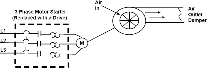
Figure 1. Fixed Speed Fan Application
A drive can control two main elements of a 3-phase induction motor: speed and torque. To understand how a Lenze VFD controls these two elements, we will take a short review of AC induction motors. The two basic parts of the motor, the rotor and stator, work through magnetic interaction. A motor contains pole pairs. These are iron pieces in the stator, wound in a specific pattern to provide a north to south magnetic field.
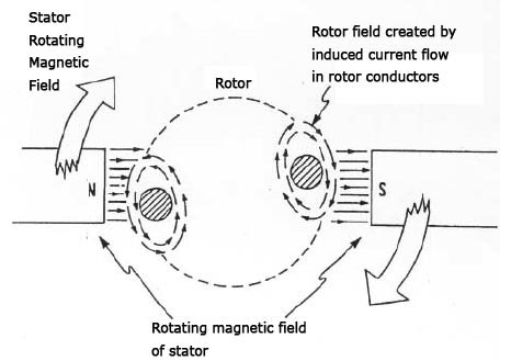
Figure 2. Operating Principles of Induction Motor
With one pole pair isolated in a motor, the rotor (shaft) rotates at a specific speed: the base speed. The number of poles and the frequency applied determine this speed (Figure 3). This formula includes an effect called "slip". Slip is the difference between the rotor speed and the rotating magnetic field in the stator. When a magnetic field passes through the conductors of the rotor, the rotor takes on magnetic fields of its own. These rotor magnetic fields will try to catch up to the rotating fields of the stator. However, it never does, this difference is slip. Think of slip as the distance between the greyhounds and the hare they are chasing around the track. As long as they don't catch up to the hare, they will continue to revolve around the track. Slip is what allows a motor to turn.
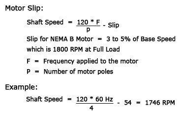
Figure 3. Induction Motor Slip Calculation
We can conveniently adjust the speed of a motor by changing the frequency applied to the motor. You could adjust motor speed by adjusting the number of poles, but this is a physical change to the motor. It would require rewinding, and result in a step change to the speed. So, for convenience, cost-efficiency, and precision, we change the frequency. Figure 4 shows the torque-developing characteristic of every motor: the Volts per Hertz ratio (V/Hz). We change this ratio to change motor torque. An induction motor connected to a 460V, 60 Hz source has a ratio of 7.67. As long as this ratio stays in proportion, the motor will develop rated torque. A drive provides many different frequency outputs. At any given frequency output of the drive, you get a new torque curve.
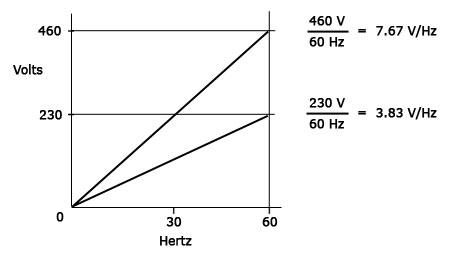
Figure 4. Volts/Hertz Ratio
How Drive Changes Motor Speed
Just how does a Lenze AC Tech drive provide the frequency and voltage output necessary to change the speed of a motor? That's what we'll look at next. Figure 5 shows a basic PWM drive. All PWM drives contain these main parts, with subtle differences in hardware and software components.
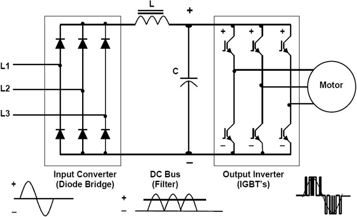
Figure 5. Basic PWM Drive Components
Although some drives accept single-phase input power, we'll focus on the 3-phase drive. But to simplify illustrations, the waveforms in the drive figures show only one phase of input and output. The input section of the drive is the converter. It contains six diodes, arranged in an electrical bridge. These diodes convert AC power to DC power. The next section-the DC bus section-sees a fixed DC voltage.
The DC Bus section filters and smoothes out the waveform. The diodes actually reconstruct the negative halves of the waveform onto the positive half. In a 460V unit, you'd measure an average DC bus voltage of about 650V to 680V. You can calculate this as line voltage times 1.414. The inductor (L) and the capacitor (C) work together to filter out any AC component of the DC waveform. The smoother the DC waveform, the cleaner the output waveform from the drive.
The DC bus feeds the final section of the drive: the inverter. As the name implies, this section inverts the DC voltage back to AC. But, it does so in a variable voltage and frequency output. How does it do this? That depends on what kind of power devices your drive uses. If you have many SCR-based drives in your facility, see the Sidebar. Bipolar Transistor technology began superceding SCRs in drives in the mid-1970s. In the early 1990s, those gave way to using Insulated Gate Bipolar Transistor (IGBT) technology, which will form the basis for our discussion.
Switching Bus With IGBTs
Today's inverters use Insulated Gate Bipolar Transistors (IGBTs) to switch the DC bus on and off at specific intervals. In doing so, the inverter actually creates a variable AC voltage and frequency output. The output of the drive doesn't provide an exact replica of the AC input sine waveform. Instead, it provides voltage pulses that are at a constant magnitude. The drive's control board signals the power device's control circuits to turn "on" the waveform positive half or negative half of the power device. This alternating of positive and negative switches recreates the 3 phase output. The longer the power device remains on, the higher the output voltage. The less time the power device is on, the lower the output voltage. Conversely, the longer the power device is off, the lower the output frequency.
The speed at which power devices switch on and off is the carrier frequency, also known as the switch frequency. The higher the switch frequency, the more resolution each PWM pulse contains. Typical switch frequencies are 3,000 to 4,000 times per second (3KHz to 4KHz). (With an older, SCR-based drive, switch frequencies are 250 to 500 times per second). As you can imagine, the higher the switch frequency, the smoother the output waveform and the higher the resolution. However, higher switch frequencies decrease the efficiency of the drive because of increased heat in the power devices.
Shrinking Cost And Size
Lenze Drives vary in the complexity of their designs, but the designs continue to improve. Drives come in smaller packages with each generation. The trend is similar to that of the personal computer. More features, better performance, and lower cost with successive generations. Unlike computers, however, drives have dramatically improved in their reliability and ease of use. And also unlike computers, the typical drive of today doesn't spew gratuitous harmonics into your distribution system-nor does it affect your power factor. Variable speed/frequency drives are increasingly becoming "plug and play". As electronic power components improve in reliability and decrease in size, the cost and size of VFDs will continue to decrease. While all that is going on, their performance and ease of use will only get better.
Sidebar: What if you have SCRs?
With the large installed base of SCRs, you might want to know how these operate. An SCR (originally referred to as a thyristor) contains a control element called a gate. The gate acts as the "turn-on" switch that allows the device to fully conduct voltage. The device conducts voltage until the polarity of the device reverses-and then it automatically "turns off".
Special circuitry, usually requiring another circuit board and associated wiring, controls this switching. The SCR's output depends on how soon in the control cycle that gate turns on. The IGBT output also depends the length of time the gate is on. However, it can turn off anytime in the control cycle, providing a more precise output waveform. IGBTs also require a control circuit connected to the gate, but this circuitry is less complex and doesn't require a reversal of polarity. Thus, you would approach troubleshooting differently if you have an SCR-based drive.