How To Install Sentrol GuardSwitch Series 129 Non-Contact Interlock/Position Switch
Edwards Signaling 12th Dec 2022
How To Install GuardSwitch Series 129 Non-Contact Interlock/Position Switch
Applies to the following part numbers and more:
129-2n-06(j) 129-2n-12(j) 129-3n-12(j) 129-6n-06(j) 129-6n-12(j) 129-7n-06(j) 129-7n-12(j) 129-9n-06(j) 129-9n-12(j) 129-6n-06(j)(d6) 129-6n-12(j)(d6) 129-6n-14(j)(d6) 129-6n-06(j)(dg) 129-6n-12(j)(dg) 129-6n-20(j)(dg)
Warning! To avoid switch failure determine the actual load of the switch circuit and take steps to protect the switch from voltage spikes, current inrush and line/load capacitance using the following recommendations.
• Surges from coils, motors, contactors, solenoids and tungsten filaments. Transient protection, such as back-to-back zener diodes (Transorb) or an RC network, is recommended for such loads to ensure that maximum ratings of the switch are not exceeded.
• Line capacitance and load capacitance. An in-line resistor can be added in series immediately before the load to limit the inrush current. The resistor can only be added in series with the last wire just before the load. The voltage drop and the power rating of the resistor must also be calculated as follows:
Voltage drop = I • R Watts = I2 • R
( I = maximum continuous current of the load)
To verify Sentrol switch operation with an ohmmeter:
Set range at 20 mega ohms (switches with triac output, set ohm range at 20 kilo ohms). For a normally open switch, the meter will read a high impedance with the actuator away. It will read very high to infinity range (triac switches will read high kilo ohm to infinity range) with the actuator within sense range. You will see the opposite reading for a normally closed GE Security switch.
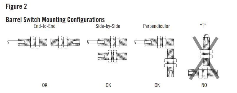
Three configurations are appropriate for recessed interlock applications. Moving the actuator parallel to the switch can result in on/off/on signal if the actuator passes by the switch rather than coming to rest in proximity to it. This is NOT a recommended configuration for interlock/position applications. The "T" configuration results in non-actuation.
Installation
1. Using the following guidelines, determine a suitable mounting location:
• The switch and actuator must be within the listed sense range. See Ordering/ Electrical Specifications.
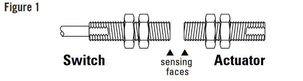
• The sense ranges are based on switch and actuator aligned so the sensing surfaces are face to face. (See Figure 1.)
Important: When mounting in proximity to ferrous material (steel), the sense range can be reduced 50% minimum depending on the shape and type of material. Test the switch in specific applications to determine the actual sense range.
• When mounting on a ferrous material (steel), a 1/4" nonferrous (plastic or aluminum) spacer may be used under the actuator and switch to restore most of the lost gap.
• When mounting on a hinged gate or door, mount the switch and actuator at least 6" away from the hinges to achieve the maximum movement.
• The switch and actuator must move in one of the approved directions. See Figure 2.
• The actuator can be mounted at a 90° rotation to the switch.
• Do not mount for parallel actuation. An on-off-on signal may result when the actuator passes by the switch.
2. Mount the switch on the stationary frame of the machine and connect the electrical wiring. When mounting the switch on an ungrounded machine, connect the ground lead to one of the mounting screws.
3. Mount the actuator on the movable guard, door, or gate.
4. Slightly over-drill holes for easy insertion. The switch and actuator should easily slide or screw into the predrilled holes – DO NOT force or hammer. This may damage switch.
Wire Color Code
Black COM
White N.O.
Red N.C.
White N.O.
Red N.C.
General Specifications
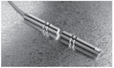
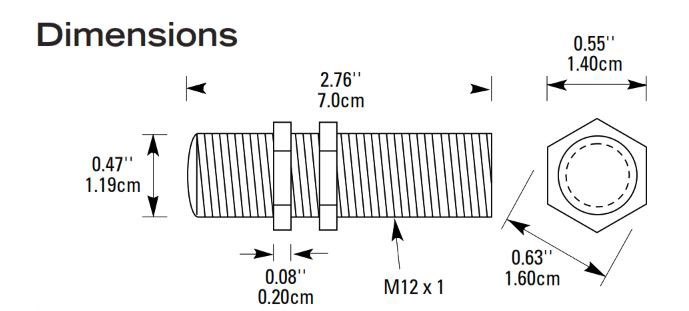
Enclosure Stainless Steel Threaded Barrel with 2 Panel Nuts
Dimensions M12 dia. x 1 Thread x 70mm Long
Temperature Range -40°F to 180°F (-40°C to 80°C)
Environmental Hermetically Sealed Contact Switch
Sealed in Polyurethane
NEMA Rating 1, 2, 3, 4X, 5, 6, 12
Protection Class IP 67
Response Time 1 msec
Life Cycles 100,000 Under Full Load;
Up to 200,000,000 Under Dry Circuit
Lead Types/O.D. 22/2 or 22/3 Flying Leads (V)/0.05" (0.13cm)
22/2 Jacketed (J)/0.16" (0.40cm)
22/3 Jacketed (J)/0.164" (0.41cm)
22/4 Jacketed (J)/0.187" (0.47cm)
18/2 Jacketed (J)/0.24" (0.62cm)
UL/CSA All Models
Ordering/Electrical Specifications
| PART NUMBER | CONTACT(1) CONFIG. | LOAD RATING AC/DC | SWITCHINGVOLTAGE MAXIMUM, AC/DC | SWITCHING CURRENT MAXIMUM, AC/DC | CONTACT RESISTANCE | LEAD LENGTH NOMINAL | WIRE SIZE |
|---|---|---|---|---|---|---|---|
| 129-2N-06(J) | SPDT | 15VA/15W | 120V@0.11A120V@0.11A | 0.5A@30V0.5A@30V | 0.2Ohms | 6'(1.8m) | 22/3 |
| 129-2N-12(J) | SPDT | 15VA/15W | 120V@0.11A120V@0.11A | 0.5A@30V0.5A@30V | 0.2Ohms | 12'(3.6m) | 22/3 |
| 129-3N-12(J) | N.C. | 100VA/84W | 120V@0.8A28V@3.0A | 3.0A@34V3.0A@28V | 0.2Ohms | 12'(3.6m) | 18/2 |
| 129-6N-06(J)-(-D6) | DPST2 | 25VA/25W | 120V@0.2A120V@0.2A | 0.7A@35V1.0A@25V | 0.2Ohms | 6'(1.8m) | 22/4 |
| 129-6N-12(J)-(-D6) | DPST2 | 25VA/25W | 120V@0.2A120V@0.2A | 0.7A@35V1.0A@25V | 0.2Ohms | 12'(3.6m) | 22/4 |
| 129-6N-12(J)-DG | DPST2 | 25VA/25W | 120V@0.2A120V@0.2A | 0.7A@35V1.0A@25V | 0.2Ohms | 12'(3.6m) | 22/4 |
| 129-6N-14(J)-D6 | DPST2 | 25VA/25W | 120V@0.2A120V@0.2A | 0.7A@35V1.0A@25V | 0.2Ohms | 14'(4.3m) | 22/4 |
| 129-6N-20(J)-DG | DPST2 | 25VA/25W | 120V@0.2A120V@0.2A | 0.7A@35V1.0A@25V | 0.2Ohms | 20'(6.1m) | 22/4 |
| 129-7N-06(J) | N.O. | 100VA/84W | 120V@0.8A120V@0.8A | 3.0A@34V33.0A@28V3 | 0.2Ohms | 6'(1.8m) | 18/2 |
| 129-7N-12(J) | N.O. | 100VA/84W | 120V@0.8A120V@0.8A | 3.0A@34V33.0A@28V3 | 0.2Ohms | 12'(3.6m) | 18/2 |
| 129-9N-06(J) | N.O. | 50VA/50W | 125V@0.4A125V@0.4A | 1.0A@50V1.0A@50V | 0.2Ohms | 6'(1.8m) | 22/2 |
| 129-9N-12(J) | N.O. | 50VA/50W | 125V@0.4A125V@0.4A | 1.0A@50V1.0A@50V | 0.2Ohms | 12'(3.6m) | 22/2 |
Warning - Each electrical rating is an individual maximum and cannot be exceeded!
1 Configuration with actuator away from the switch
2 D6=DPST: 2 N.O., DG=DPST: 1 N.O., 1 N.C.
3 Rated at 3.0A for 6,000 cycles only. Other ratings are at 100,000 cycles
2 D6=DPST: 2 N.O., DG=DPST: 1 N.O., 1 N.C.
3 Rated at 3.0A for 6,000 cycles only. Other ratings are at 100,000 cycles
Sense Range(4)
| ACTUATOR | 129-2, 129-G OR -DG | 129-2, 129-G OR -DG | 129-6 or -D6 | 129-6 or -D6 | 129-9 or -D9 | 129-9 or -D9 | 129-7 or 129-3 | 129-7 or 129-3 | ACTUATOR |
|---|---|---|---|---|---|---|---|---|---|
| OPTIONS | Make, Min. | Break, Max. | Make, Min. | Break, Max. | Make, Min. | Break, Max. | Make, Min. | Break, Max. | DESCRIPTION |
| 128C-U | 0.25 | 0.8 | 0.15 | 1 | 0.1 | 0.7 | NA | NA | Alnico Magnet in M8x1.25x50 stainless steel threaded barrel w/2 jam nuts |
| 129-X | 0.45 | 1.1 | 0.35 | 1.35 | 0.25 | 1 | 0.15 | 0.9 | Alnico Magnet in M12x1x70 stainless steel threaded barrel w/2 panel nuts |
| 1057 | 0.9 | 1.75 | 0.85 | 2.15 | 0.7 | 1.7 | 0.55 | 1.4 | Bare Alnico Magnet 3/8" dia. x 1-1/2" long |
| IND1835 | 0.5 | 0.85 | 0.4 | 1 | 0.3 | 0.8 | 0.2 | 0.7 | Rare Earth 0.6" dia. x 0.12" thick w/#4 countersink hole |
4 Proximity of ferrous materials usually reduces sense range - typically by 50%. The shape and type of material cause a wide diversity of effects. Testing is required to determine actual sense range for specific applications.
12th Dec 2022