How To Install Sentrol GuardSwitch Series 251-F6 and F7 Non-Contact Safety Interlock Switch
Edwards Signaling 12th Dec 2022
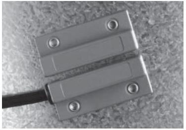
How To Install GuardSwitch Series 251-F6 and F7 Non-Contact Safety Interlock Switch
Applies to the following part numbers and more:
251-F6Z-06K 251-F6Z-12K 251-F6Z-14K 251-F7Z-06K 251-F7Z-12K
Warning! To avoid switch failure determine the actual load of the GE Security switch circuit and take steps to protect the switch from voltage spikes, current inrush and line/load capacitance using the following recommendations. If the installation instructions are not followed carefully, the switch may not work properly or fulfill its failsafe function, or it may fail prematurely.
1. Surges from coils, motors, contactors, solenoids and tungsten filaments must be considered.
2. Transient protection, such as back-to-back zener diodes (Transorb) or an RC network, is recommended for such loads to ensure that maximum ratings of the switch are not exceeded.
3. Line capacitance and load capacitance must be considered. An in-line resistor can be added to limit the inrush current.
4. The resistor can only be added in series with the last red wire just before the load.
5. The voltage drop and the power rating of the resistor must be considered.
Voltage drop = I • R
Watts = I2 • R
(I = maximum continuous current of the load)
Dimensions
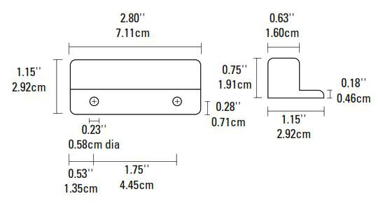
Figure 1
Installation
Use non-removable screws, bolts, or nuts to mount the Sentrol switch and actuator. Do not over-torque mounting hardware.
1. Do not wire the Interlogix switch until it is mounted and tested. (See Testing/Wiring)
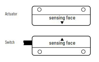
2. Select a mounting location where the switch and actuator can be installed with their labels reading in the same direction. (See Figure 1.)
3. Mount the switch on the stationary frame of the machine and the actuator on the moveable guard, door or gate.
4. For best protection against operator defeat, mount with non-removeable screws, bolts, or nuts. (See accessories)
5. The switch and actuator must be mounted so that the actuator moves in one of the approved directions. (See Mounting Configuration, Figure 2)
6. Parallel actuation is NOT recommended and may cause switch failure. An on/off/ on signal may result when the magnet passes by the switch rather than coming to rest in proximity to it. (See Mounting Configuration, Figure 2)
7. When mounting on a hinged gate or door, mount the switch and actuator at least 6" away from the hinges so a more parallel movement is achieved.
8. The actuator can be mounted at a 90° rotation.
9. Keep the switch and actuator within the listed sense range (See Ordering/ Electrical Specifications).
10. Mounting on a ferrous (steel) material will reduce the sense range a minimum of 50%. A 1/4" nonferrous (plastic or aluminum) spacer installed under the actuator and switch will restore most of the lost gap.
11. When mounting a metal switch to an ungrounded machine, connect the ground lead to one of the switch mounting screws.
Mounting Configurations
Figure 2
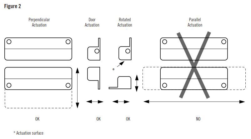
* Actuation surface
Three configurations are appropriate for interlock applications. The parallel actuation can result in on/off/on signal if the actuator passes by the switch rather than coming to rest in proximity to it. This is NOT a recommended configuration for interlock applications.
Wiring for one FailSafe GuardSwitch
Add a 1/2 amp fast-acting fuse in series to protect the switch from premature failure caused by inrush-currents, tampering, or excessive vibration.
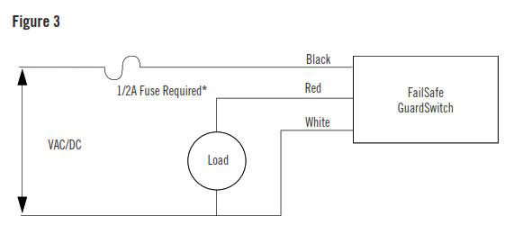
* Use fast-acting Littlefuse 216, fast-acting Microfuse or fast-acting Pico II fuse up to 1/2 Amp.
Wiring for two to ten FailSafe GuardSwitches in series
Add a 1/2 amp fast-acting fuse in series to protect the switch from premature failure caused by inrush-currents, tampering, or excessive vibration.
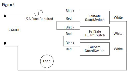
* Use fast-acting Littlefuse 216, fast-acting Microfuse or fast-acting Pico II fuse up to 1/2 Amp.
Testing
After mounting the switch and actuator, test the switch for proper operation. Test with circuit disconnected from source and load. For multiple switches in series, test one switch at a time with all other guard doors closed. Then:
1. Hook the black and white leads of the switch to an Ohmmeter. Move the gate or door open and closed several times slowly. At all times the meter should read O.L. or "open."
2. Hook the Ohmmeter to the black and red leads of the switch. Move the door or gate open and closed. The meters should read O.L. when the actuator is away and it should read less than 1 Ohm when the actuator is in range.
3. Hook the Ohmmeter to the white and red leads of the switch. Move the door or gate open and closed. The meter should read 11–14 ohms (F6 model) and 500-100 ohms (F7 models) when the actuator is away and it should read O.L. when the actuator is in range.
Wiring
1. After the switch and actuator have been mounted and tested, wire the FailSafe GuardSwitch as shown in Figure 3.
2. For wiring 2 to 10 FailSafe GuardSwitches in series, see Figure 4. (Do not exceed 10 switches in a series).
3. Failure to install in-line fuse voids warranty.
Troubleshooting
If the in-line fuse blows or the GuardSwitch remains open:
1. Check the application for premature failure caused by inrush-currents, tampering, excessive vibration and misalignment.
2. Disconnect all three wires of GuardSwitch and test according to testing instructions, steps 1-3.
3. If the GuardSwitch fails any of the three tests, it must be replaced.
4. Replace the in-line fuse if blown.
General Specifications
Enclosure Polyurethane Enamel-Coated Aluminum
Temperature Range -40°F to 150°F (-40°C to 65°C)
Environmental Hermetically Sealed Contact Switch, Encapsulated in Polyurethane
NEMA Rating 1, 2, 3, 4, 4X, 5, 6, 12
Protection Class IP 67
Response Time 5 msec
Life Cycles 100,000 Under Full Load;
Up to 200,000,000 Under Dry Circuit
Lead Types/O.D. SJTOW-A (K) 18/3 AWG/0.33" (0.83cm)
UL/CSA All Models
Note: The 251 & 253-F7 has a patented “watch-dog” circuit which, when switch failure occurs, the fused watch-dog circuit will draw 4 Amps. The voltage supply must have a current capacity of 4 Amps. This results in an open, fail-safe condition.
Accessories
PART NUMBER TAMPER PROOF SCREWS & SCREWDRIVER
1954 #8 x 1-1/2"L Tampruf Roundhead Screw
1955 Tampruf Screwdriver
1956 Tampruf 1/4" Drive Bit for #6 and #8 Screws
Ordering/Electrical Specifications
| PART NUMBER (1) | CONTACT CONFIG. (2) | LOAD RATING MAXIMUM | SWITCH CURRENT MAXIMUM AC/DC | VOLTAGE RANGE AC/DC | CONTACT RESISTANCE | SENSE RANGE NOMINAL (3) | BREAK RANGE NOMINAL | BREAK AT FAILURE MAX. | LEAD LENGTH NOMINAL |
|---|---|---|---|---|---|---|---|---|---|
| 251-F6Z-06K | N.O. | 12W/VAC | 0.5A | 24±4V | 0.5 Ohms | 1.0" (2.5cm) | 2.2" (5.6cm) | 3.0" (7.6cm) | 6'(1.8m) |
| 251-F6Z-12K | N.O. | 12W/VAC | 0.5A | 24±4V | 0.5 Ohms | 1.0" (2.5cm) | 2.2"(5.6cm) | 3.0"(7.6cm) | 12'(3.6m) |
| 251-F6Z-14K | N.O. | 12W/VAC | 0.5A | 24±4V | 0.5 Ohms | 1.0" (2.5cm) | 2.2"(5.6cm) | 3.0"(7.6cm) | 14'(4.2m) |
| 251-F7Z-06K | N.O. | 100VA | 0.83A | 100-120V AC | 0.5 Ohms | 1.0'(2.5cm) | 1.8' (4.5cm) | 2.T' (6.8cm) | 6'(1.8m) |
| 251-F7Z-12K | N.O. | 100VA | 0.83A | 100-120V AC | 0.5 Ohms | 1.0' (2.5cm) | 1.8' (4.5cm) | 2.T' (6.8cm) | 12'(3.6m) |
Warning - Each electrical rating is an individual maximum and cannot be exceeded!
1 The part number 253 is the same as 251 in all respects, except the cable exits 251 left and 253 right.
2 Configuration with actuator away from the switch
3 Proximity of ferrous materials usually reduces sense range - typically by 50%. The shape and type of material cause a wide diversity of effects. Testing is required to determine actual sense range for specific applications.
2 Configuration with actuator away from the switch
3 Proximity of ferrous materials usually reduces sense range - typically by 50%. The shape and type of material cause a wide diversity of effects. Testing is required to determine actual sense range for specific applications.
12th Dec 2022