Frequently Asked Questions For IDEC Programmable Logic Controllers (PLC)
IDEC Corporation 12th Dec 2022
 Can I use the analog input and/or output at the same time as the high speed counter on Micro PLCs?
For models that include both of these features, you can use an Analog Output along with the HSC. However, you cannot use the Analog Input with the HSC since the Analog Input uses the same input (I0) as the HSC. Please note that to use the Analog Output one has to use a Transistor output unit.
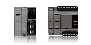
What is the difference between the Micro-3 and Micro-3C?
The Micro-3C has additional communications abilities, including two serial ports, RS232 and RS485, dial-up capabilities, and additional data registers.
Can IDEC PLCs be operated over a wireless link?
Our Micro3C, ONC and Microsmart PLCs can be used over a wireless radio modem, and have the ability to communicate in ASCII and initiate modem dialing commands.
I need to program an FA PLC (FA1J, FA2J, FA3S). What cables/adaptors do I need from PC to FA series?
You will need to purchase 2 cables and a link adaptor. Part numbers are as follows:
PFA-1A51 (cable from FA to link adaptor)
PF2-CLA (link adaptor)
PFA-1A54A(cable from link adaptor to PC)
Which cable can I use if the CPU or I/O module has MIL connector type?
If the I/O module is MIL connector type, use cable part number FC9Z-H###B20/A20 plus a breakout module part number BX1D-S20A. For the CPU with MIL connector, use cable part number FC9Z-H###A26/B26 and breakout module BX1D-S26A. Please check brochure/catalog for complete cable part number.
Do any of our PLCs support Modbus?
Yes, both Microsmart and ONC support Modbus RTUs when used with the IDEC-MODBUS converter. The part numbers are as follows:
Converter (FC2A-GWY-025-009-V00)
Software (FC2A-MBUS-SOFT)
Programming cable (FC4A-MBUS485)
Package (IDEC-MBUS-CONVPCK)
How do I download a Micro3 program from the PC to the loader?
A program can be downloaded to the loader by following these steps:
Change the data length in the communication settings dialog to 7
In the Download Dialog, change the "Download to:" from "PLC" to "Loader"
On the Loader, press TRS, down arrow
Make sure the screen reads "Loader to PC OK?"
In the Download Dialog, press OK
On the Loader, press ENTR.
A message box should appear on the PC saying "Program Download Succeeded". The loader screen will say, "Loader to PC END".
How do I communicate with more than one Micro-1 PLC?
You can communicate with more than one Micro-1 or FA Series PLC by using the 1:N communication function within WindLDR. Follow these steps:
1. Each PLC should be given a unique device number. Each device number can be checked using the loader.
2. Attach the loader to the Micro-1.
3. Press FUN, enter 60, and press the READ key. The device number will appear in the far right corner of the screen. If that is the desired device number, remove the loader and attach the PLC to the cable link. If it is not, or you want to change the number, enter the desired number.
4. Press the TRS key, then the ENTR key. The screen should say "TRS LTP GO?".
5. Press the "ENTR" key. The new device number has been assigned. All PLCs to be used in the 1:N communication settings should be checked.
6. The PLC Network Settings in the communication Settings Dialog should be set to 1:N.
7. The Device number in the communication Settings Dialogue should be set to the PLC that will be communicated with.
8. To download the program to each PLC, the device number in the communication dialog has to be set to that PLC device number.
9. The 1:N Communication Device No. in the Function Area Settings Dialogue should also be changed to the PLC device number.
10. The user should then open the download dialog and press OK. At this time the program should be downloaded to the assigned PLC.
What is the programming cable for use with the Micro-1?
The Micro-1 communication cable, from the Micro1 to a PC serial port, is FC1A-CLA.
How do I communicate with more than one Micro3 Series PLC?
You can communicate with more than one Micro3 series PLC by using the 1:N communication Function within WindLDR. The steps below can be followed to achieve this:
Each PLC should be given unique device number. Each PLC device number can be checked using the loader.
Attach the loader to the Micro3.
Press FUN, enter 9, and press the Down Arrow key. The device number will appear at the bottom of the screen. If that is the desired device number, remove the loader and attach the PLC to the cable link. If it is not the correct device number or you want to change the number, press the Down Arrow key, enter the desired number and press the enter key.
Press the TRS key, then the ENTR key. The screen should say "Loader to PC OK?".
Press the "ENTR" key. The new device number has been assigned.
All PLCs to be used in the 1:N communication settings should be checked.
The PLC Network Settings in the Communication Settings Dialogue should be set to 1:N.
The Device Number in the Communication Settings Dialogue should be set to the PLC that is going to be communicated with.
The 1:N Communication Device No. in the Function Area Settings Dialog, should also be changed to the PLC device number.
Open the download dialogue and press OK.
At this time the program should be downloaded to the assigned PLC.
How do I upload a Micro3 program from the loader to the PC?
A program can be uploaded to the PC by following these steps:
In the PLC selection dialogue, select the Micro3 PLC. Click OK.
In the upload Dialogue, change the "Upload From:" from PLC to Loader.
On the Loader, press TRS, ENTR. Make sure the screen reads " Loader to PC OK?"
In the upload Dialog, press OK.
On the Loader, press ENTR.
A message box should appear on the PC saying "Program upload Succeeded". The loader screen will say, "Loader to PC END". When the message box comes up saying that the program was successfully uploaded, another dialog box will appear after the OK button is clicked. The message box will read, "Wait for conversion to ladder". It is very important that you do not press the OK button in the message box until the message box blinks. If you do press the OK button before the box blinks an error will appear telling you that the mnemonic to ladder conversion has failed.
Can you monitor IDEC PLCs remotely? If so, what would be the longest hardwire length?
Using regular communication cables the approximate distance is about 15 feet. But if you use a modem with a dedicated phone line, you can monitor, download, upload or do any changes to your program from anywhere in the world.
Can IDEC PLCs be operated over a wireless link?
Our Micro3C, ONC and Microsmart PLCs can be used over a wireless radio modem, and have the ability to communicate in ASCII and initiating modem dialing commands.
12th Dec 2022