Frequently Asked Questions For Kubler Products and Technologies
Kubler 12th Dec 2022
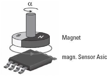
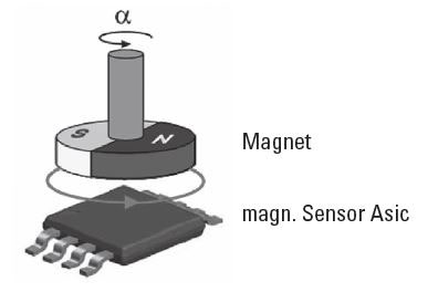
Absolute encoders magnetic scanning
The magnetic field created by a rotating permanent magnet is scanned by a sensor Asic. Each angular position has underlying field vectors, which are converted by the Asic into an electrical signal.
Depending on the version, this output signal can be either SSI, 0… 10V, 4… 20mA or Fieldbus.
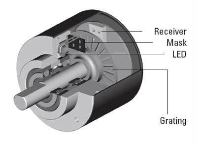
Absolute encoders optical scanning
The light that is emitted by an LED is modulated by a code pattern, which is applied to a rotating disc; this is scanned by a special Ku¨bler Opto ASIC. A unique bit pattern is assigned to each position and this is generally available as Gray Code.
The advantage, compared with incremental encoders, lies in the fact that any movement of the shaft whilst voltage is not applied is immediately detected when power is re-applied, ensuring the correct position is always available.
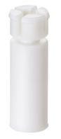
Adapter inserts
By using these adapter inserts you can achieve six different hollow shaft diameters, all on the basis of one encoder.
Adding
The counter starts from zero and counts up to the programmed preset value, at which an output signal is triggered. The counter is then reset to zero - this can be programmed to happen automatically. The current count value is always displayed.
Adding pulse counter
Add the incoming impulses continuously. They are available with or without electrical or manual reset. Miniature counters are also available for battery operation with a power consumption of only 50 or 30 mW and are protected against shock and vibration to a very high extent.
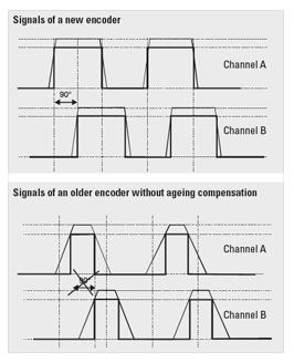
Aging compensation
Every LED loses some of its luminosity over time. Without ageing compensation the excellent quality of the output signals would suffer. The phase shift of 90° necessary to detect the direction of rotation would be lost. This effect however is prevented by means of special electronic circuitry.
Benefit: The ageing compensation circuit ensures the same signal, even after many years of operating time. The downtime of machines will be reduced dramatically and the reliability is increased.
Ambient temperature
Is the permissible temperature within the direct vicinity of the pulse counter. When using the counters in groups, the reciprocal heating must be taken into consideration as this results in an ambient temperature rise. The upper or lower value is only applicable to the rated voltage.
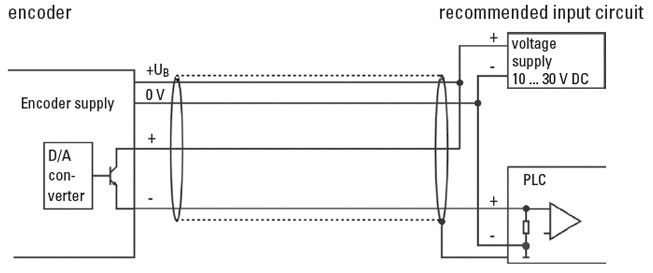
Analogue output 4 ... 20 mA
Output circuit and recommended input circuit
ATEX (ATmosphere EXplosible)
Since 30/06/2003, all new installations used in explosion protected areas have to be built according to the directive 94/9/EG (ATEX 100a).
Bearing life
All Kübler encoders are designed to ensure that their bearings give a long service life. This is subject of course to correct installation and to the load limits for the shaft (shaft encoders) being complied with or, in the case of hollow shaft encoders, being mounted with the appropriate stator couplings or torque stops.
The following diagrams show the expected service life of the shaft encoder bearings depending on the bearing load. The calculations are based on a mixed load, where the axial force components are always half of the radial shaft load.
The use of the torque stops and stator couplings that are offered ensure that the shaft load with the hollow shaft encoders as supplied from the factory is kept very small.
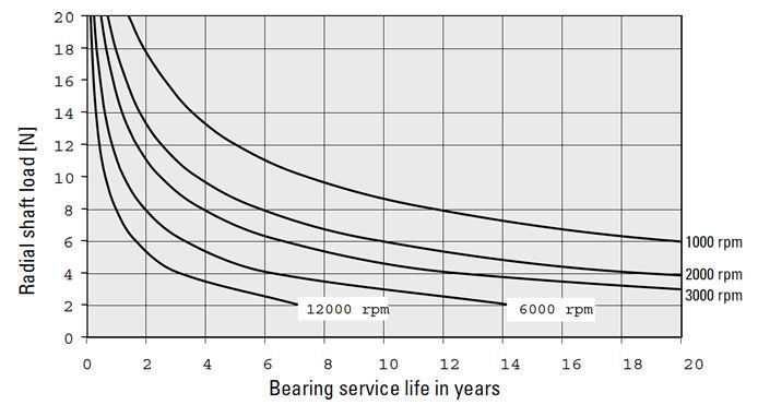
Bearing life for shaft encoders Type 2400
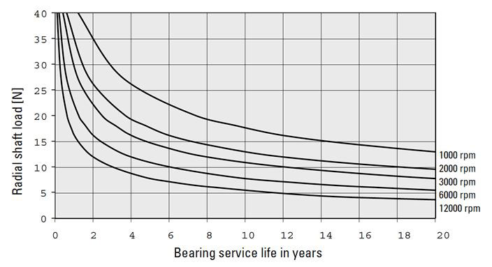
Bearing life for shaft encoders Type 36x0
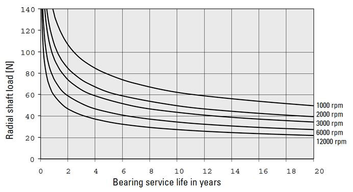
Bearing life for shaft encoders Type 3700
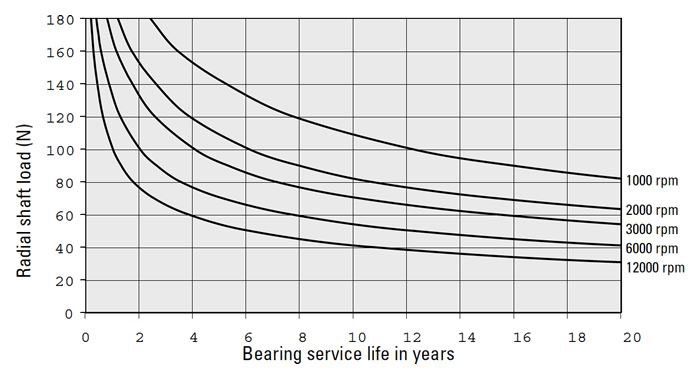
Bearing life for shaft encoders of the Sendix series
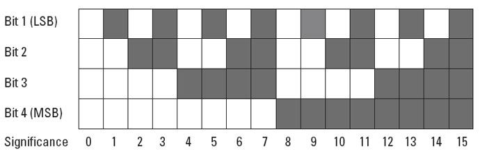
Binary Code
The Binary Code can be processed very easily by computer systems. When using optical read-out, errors may occur, because the change from one bit to another on the different concentric tracks (LSB, LSB+1...) is not exactly synchronized. Due to this, without any correction of the code, the position information could be wrong.
BiSS Interface
Open, digital sensor interface (BiSS-C)
• Easy integration with the assistance of the Kübler experts team
• The existing standard control hardware can be used
• Open Source
• Real-time feedback of position and speed
• 100 times faster than standard field bus systems
• Fully digital and bi-directional
• The existing standard control hardware can be used
• Open Source
• Real-time feedback of position and speed
• 100 times faster than standard field bus systems
• Fully digital and bi-directional

Bit (Binary Digit)
Smallest discrete piece of information. A bit can be allocated to the value 0 or 1.
Cable lengths for absolute encoders
Cable length: the following maximum cable lengths are recommended, depending on the output circuitry and any noise sources present:
Interface And Output Circuit: Parallel CMOS/TTL
Max. Cable Length: 2 m
Connected To: SPS / IPC (1)
Max. Cable Length: 2 m
Connected To: SPS / IPC (1)
Interface And Output Circuit: Parallel push-pull
Max. Cable Length: 100 m
Connected To: SPS / IPC (1)
Max. Cable Length: 100 m
Connected To: SPS / IPC (1)
Interface And Output Circuit: SSI
Max. Cable Length: Up To 1000 m
Connected To: SPS / IPC (1)
Max. Cable Length: Up To 1000 m
Connected To: SPS / IPC (1)
Interface And Output Circuit: RS 422 /RS 485
Max. Cable Length: 1000 m
Connected To: SPS / IPC (1)
Max. Cable Length: 1000 m
Connected To: SPS / IPC (1)
Interface And Output Circuit: Analogue 4 ... 20 mA
Max. Cable Length: 200 m
Connected To: -
Max. Cable Length: 200 m
Connected To: -
Annotations:
• Depending on the application the max. allowed cable length can be shorter, especially in areas with strong electrical noise.
• Always use shielded cables.
• The core diameter of the signal cores should be ≥ 0.14 mm².
• The core diameter of the voltage supply cores should be large enough depending on the cable length, that the voltage supply of the encoder is high enough and the signals do not go below the minimum levels!
• We strictly recommend the use of the cable types written down in the accessories.
(1) IPC = Industrial PC
(2) Depends on clock frequency: at 100 kHz Lmax approx. 250 m; at f = 250 kHz Lmax approx. 50 m
(2) Depends on clock frequency: at 100 kHz Lmax approx. 250 m; at f = 250 kHz Lmax approx. 50 m
Cable lengths for incremental encoders
Depending on the output circuit and the electrical noise the following cable lengths are recommended:
Output Circuit: Push-pull without inverted signals
Max. Cable Length: 100 m *
Encoder Connected To E.G: Ku¨bler counter/SPS
Max. Cable Length: 100 m *
Encoder Connected To E.G: Ku¨bler counter/SPS
Output Circuit: Push-pull with inverted signals
Max. Cable Length: 250 m *
Encoder Connected To E.G: SPS / IPC (1)
Max. Cable Length: 250 m *
Encoder Connected To E.G: SPS / IPC (1)
Output Circuit: Push-Pull with inverted signals (7272)
Max. Cable Length: 30 m *
Encoder Connected To E.G: -
Max. Cable Length: 30 m *
Encoder Connected To E.G: -
Output Circuit: RS422 with inverted signals
Max. Cable Length: up to 1000 m (> 50 m dep. on frequency)
Encoder Connected To E.G: SPS / IPC (1)
Max. Cable Length: up to 1000 m (> 50 m dep. on frequency)
Encoder Connected To E.G: SPS / IPC (1)
Output Circuit: Voltage sine with inverted signals
Max. Cable Length: 50 m
Encoder Connected To E.G: SPS / IPC (1)
Max. Cable Length: 50 m
Encoder Connected To E.G: SPS / IPC (1)
Output Circuit: Sine wave 1 Vss
Max. Cable Length: 50 m
Encoder Connected To E.G: 10 ... 30 V DC
Max. Cable Length: 50 m
Encoder Connected To E.G: 10 ... 30 V DC
Annotations:
• Depending on the application the recommended cable length can be shorter, especially in areas with a high level of electrical noise.
• Always use shielded cables - the shield should be connected at both the encoder and controller ends!
• The core diameter of the signal cores should be > 0.14 mm2².
• The core diameter of the voltage supply cores should be large enough depending on the cable length, that the voltage supply of the encoder is high enough and the signals do not go below the minimum levels!
(1) Depends on frequency
(2) IPC = industrial PC
(2) IPC = industrial PC
Cables material information
PVC
• Suitable for average mechanical stresses in the area of packaging machines and assembly and production lines
• Good resistance against acids and alkalis and thus predestined for use in the food and beverage industry
• Limited friction resistance and partial resistance to oils and chemicals
• Good resistance against acids and alkalis and thus predestined for use in the food and beverage industry
• Limited friction resistance and partial resistance to oils and chemicals
PUR
• Flexible, PVC, silicone and halogen-free control cable with PUR cable jacket and polypropylene wire insulation
• The cable is oil-resistant and non-flammable according to VDE 0472, and it is resistant to chemicals, hydrolysis and microbes
• Temperature resistance from -30°C to + 90°C
• Use is possible in trailing cable carriers with a bending radius equal at least to 10 x D
• Thanks to its resistance to welding sparks, this cable is very well adapted for flexible use in the area of robotics, machine tools and metal cutting production
ccw (counter clockwise)
Turning the encoder shaft in counterclockwise direction (in view of the shaft side of the encoder).
Connection Technology
Connection Technology from Kübler = System Safety!
All the products in the Connection Technology section have been tested and approved with the relevant compatible Kübler sensors. They ensure the full functionality and high signal quality of our sensors - this guarantee is supported by our competent customer service.
Your benefit:
• Elimination of connection errors – no laborious fault finding
• Optimal shielding – avoids EMC problems
• Shorter installation times – saves time, cuts costs
• No time-consuming search for the right connector or cable – saves time, eliminates errors
• Optimal shielding – avoids EMC problems
• Shorter installation times – saves time, cuts costs
• No time-consuming search for the right connector or cable – saves time, eliminates errors
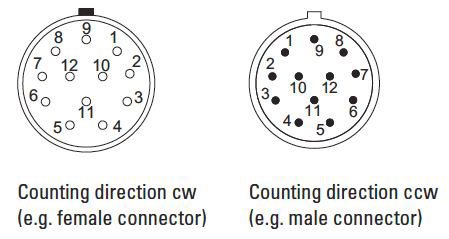
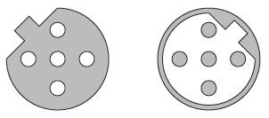
Connectors counting direction cw/ccw
The counting direction of the connectors is indicated by cw for a clockwise arrangement and ccw for a counter-clockwise arrangement. The connector is always viewed from the mating side.
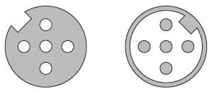
Connectors M12 coding
The connectors are coded to guarantee protection against polarity reversal. This coding is achieved by means of a peg or a notch in the contact carrier. Kübler connectors make a distinction between A, B or D coding.
A-Coding
Female connector with coupling nut: Coding notch
Male connector with external thread: Coding peg
Use: CANopen and 8-pin connector
Male connector with external thread: Coding peg
Use: CANopen and 8-pin connector
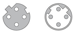
B-Coding
Female connector with coupling nut: Coding peg
Male connector with external thread: Coding notch
Use: Profibus
Male connector with external thread: Coding notch
Use: Profibus
D-Coding
Female connector with coupling nut: Coding peg and Coding notch
Male connector with external thread: Coding peg and Coding notch
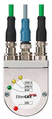
Use: Profinet and EtherCat
Male connector with external thread: Coding peg and Coding notch
Use: Profinet and EtherCat
Connectors material information
Two material groups are used for the connectors described in the catalogue:
Metals for contacts and housings
• Contacts: Metal, CuZn, gilded
• Connecting nut /compression screw: Metal, CuZn, nickel-plated
• Connecting nut /compression screw: Metal, CuZn, nickel-plated
Plastics for insulator and housing
• Contact carrier: Plastic, TPU, black
• Body: Plastic, TPU, black
• Seal: Plastic, fluorine rubber (FKM/FPM) FPM/FKM or nitrile-butadiene rubber (NBR)
• Body: Plastic, TPU, black
• Seal: Plastic, fluorine rubber (FKM/FPM) FPM/FKM or nitrile-butadiene rubber (NBR)
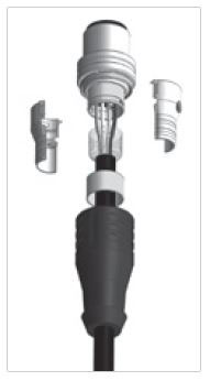
Connectors shielding
With round connectors, care must be taken to connect carefully the shielding braid of the cable to the shield connection of the connector.
An all-round contact (360°) is optimal. Good (in practice often sufficient) shielding values are also reached by connecting the shielding braid firmly to the electrically conductive housing. Connectors purely out of plastic, without metal sleeve, providing no contact for the shielding braid, are not sufficient.
Furthermore, a proper contact with the mating connector is also important, as well as a good contact of the mating connector with the chassis of the equipment.
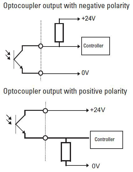
Counter outputs
We offer our preset counters with various output options: relay, transistor and optocoupler.
Relays should not be used when switching very small loads. Transistor or optocoupler outputs are better suited to operate the input of a controller. The design of both outputs is basically almost the same. However with the optocoupler, galvanic isolation is achieved between the unit (counter) and the peripheral (controller) because of an LED and a phototransistor (in one housing).
As a rule, with the optocoupler output the emitter and the collector are brought out and may have to be switched externally. Using the appropriate circuit it is possible to achieve either negative polarity (normally closed function) or positive polarity (normally open function).
cw (clockwise)
Turning the encoder shaft in clockwise direction (in view of the shaft side of the encoder).
Designation of colours
Designation of colours to DIN IEC 757
BK black
BN brown
RD red
OG orange
YE yellow
GN green
BU blue
VT violet
GY grey
WH white
PK pink
GD gold
TQ turquoise
SR siver
BN brown
RD red
OG orange
YE yellow
GN green
BU blue
VT violet
GY grey
WH white
PK pink
GD gold
TQ turquoise
SR siver
Digital outputs
The sine wave signal from the optical system is first digitised to have square wave signals available.
• Shaft turning clockwise, top view of shaft
• Inverted signals are available
• 0 pulse is linked to AND with channel A and B
• Shaft turning clockwise, top view of shaft
• Inverted signals are available
• 0 pulse is linked to AND with channel A and B
To transmit the signals there are two possible outputs available. RS422 (TTL compatible) or push-pull. When choosing the suitable output for the application the following points have to be considered:
• The corresponding unit / controller the encoder will be connected to
• The required cable length
• Dihe sensitivity against electrical noise or other interference
• The required cable length
• Dihe sensitivity against electrical noise or other interference
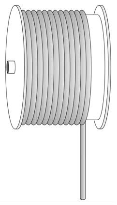
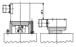
Draw wire system
The idea
At the core of a draw wire encoder is a drum mounted on bearings, onto which a wire is wound. The winding takes place via a spring-loaded device. The number of revolutions is measured by means of an encoder. If the circumference of the drum is known, then the length can be calculated from it.
• Specially for demanding applications
• With analogue sensors (0 ... 10 V, 4 ... 20 mA, potentiometer) or encoders (incremental, absolute, fieldbus)
• Measuring lengths from 250 mm up to 40000 mm
• High travelling speed
• High acceleration
• Dynamic spring traction by means of a constant force spring, long service life
• Simple wire fixing using clip
• Quick mounting
• Diamond-polished ceramic guide
• Titanium anodised aluminium housing
Electrical reset
Counters with electrical reset have an electromagnet which is operated by a reset pulse, and resets the number wheels back to the starting number. With remote reset via a pulse, the pulse duration must be long enough for the reset operation to be completed and for the minimum pulse duration to be maintained in accordance with the technical data of the counters.
It is essential that during resetting no pulses may pass into the count mechanism, as otherwise intermediate positions of the number wheel or slippage of the drive mechanism can occur. There is no danger of mechanical damage of the counter, however.
In order to avoid mistakes, the count pulses should only be allowed to enter, when the number wheels have been accurately adjusted and the drive mechanism is fully engaged. With remote reset a count interval of at least 50 ms after pulse end is required and thus the total count interval = reset pulse time + 50 msec.
Electromechanical pulse counter
The general counter construction consists of an electromagnetic drive and a mechanical kind of number wheel system. Electrical impulses cause a step-by-step revolution of the number wheels.
Encoders
Encoders can be used in applications, where length, positions, speed or an angular position are measured. They transform mechanical movements into electrical signals and can be divided into incremental and absolute measuring systems.
Incremental encoders generate pulses,where the number of pulses can be a measure of speed, length or position.
In absolute encoders, every position corresponds to an unique code pattern, so that even after a power cut the actual position is recognised, when power is re-applied.
In absolute encoders, every position corresponds to an unique code pattern, so that even after a power cut the actual position is recognised, when power is re-applied.
Encoders with one output channel
Encoders with one output channel are used where no direction sensing is needed, e.g. speed control or length measuring.
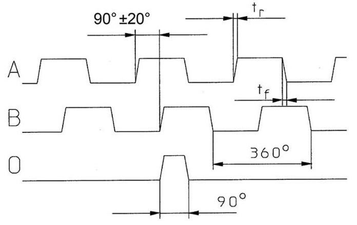
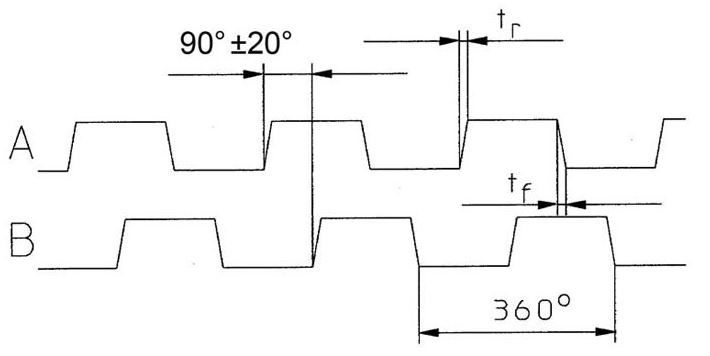
Encoders with three output channels
In addition to the two channels A and B a zero pulse is available, which occurs once per revolution and is usually used for the reference run (zero point calibration) of a machine.
• Shaft turning clockwise, top-view of shaft / for hollow shaft encoders, viewing the flange
• Inverted signals available
• 0 pulse is linked to AND with channel A and B
• Inverted signals available
• 0 pulse is linked to AND with channel A and B
tr = rise time
tf = fall time
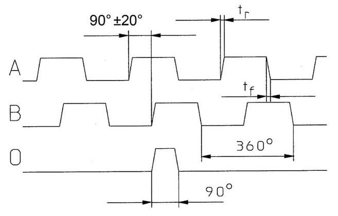
Encoders with two output channels
Applications, where the direction of rotation should be sensed, e.g. positioning, require encoders with two channels A and B being shifted 90° out of phase. By detecting the phase shift, the direction can be determined.
• Shaft turning clockwise, top-view of shaft / for hollow shaft encoders, viewing the flange
• Inverted signals available
• Shaft turning clockwise, top-view of shaft / for hollow shaft encoders, viewing the flange
• Inverted signals available
tr = rise time
tf = fall time
Fieldbus
A Fieldbus is an industrial communication system linking numerous sensors and actors to a controlling device.
Functional Safety
Kübler offers many new products with integrated safety solutions, including:
• Certified SIL2/PLd and SIL3/PLe absolute and incremental encoders
• New safety modules for safe drive monitoring
• New control solutions for safe processing of safety sensors
• New safety modules for safe drive monitoring
• New control solutions for safe processing of safety sensors
Kübler Safe Drive Monitoring and Safety Control Solutions with certified SIL2/PLd and SIL3/PLe encoders and Safety M modules, featuring:
• Easy realization of the European directive for machine 2006/42/EG
• Simple to integrate on the standard control environment
• User-friendly programming with logic chart and bloc function
• Simple to integrate on the standard control environment
• User-friendly programming with logic chart and bloc function
Gray Code
The Gray Code is a single-step code, which guarantees that from one position to the next only 1 bit changes.
This leads to reliable scanning of the code and consequently of the positions.
This leads to reliable scanning of the code and consequently of the positions.
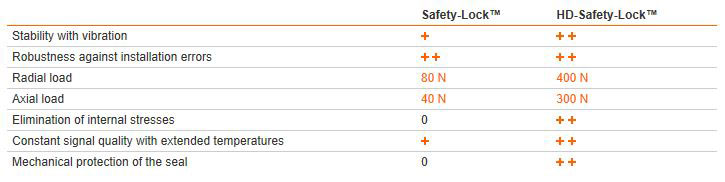
HD-Safety-Lock
Safety-Lock becomes HD-Safety-Lock
Safety-Lock
• mechanically interlocked bearings
• large, extra-strong outer bearings
• larger bearing span
• mechanically interlocked bearings
• large, extra-strong outer bearings
• larger bearing span
Benefits: Avoids premature damage or even encoder failure in the field.
HD-Safety-Lock = Safety-Lock + additional engineering
• Floating bearing on the cover-side eliminates internal stress
• Mechanically decoupled sensor unit ensures constant signal quality with large temperature fluctuations and other adverse environmental influences
• Dual seals on the shaft-side - friction seal against humidity, labyrinth seal against dust and water jet ingress
• Very large, highly-robust flange bearings
• Even greater bearing clearance
Benefits: The resistance against adverse environmental conditions is greatly increased - especially against high bearing loads and high temperatures.
Inclinometers
Inclinometers are used to measure deviations with respect to a horizontal rotary axis on an angular range up to 360°. Kuebler inclinometers are based on the MEMS technology (micro electro-mechanical system).
Incremental encoders magnetic scanning
The magnetic field created by a rotating permanent magnet is scanned by a sensor Asic. Each angular position has underlying field vectors, which are converted by the ASIC into incremental signals.
Incremental encoders optical scanning
A disc fitted with a grating, having a code pattern of slits and bars, is mounted so that it can rotate between an LED and a receiver.
The light emitted by the LED is modulated by the mask and grating and then strikes the receiver, which produces a signal proportional to the luminosity.
When the disc rotates this signal has a shape that approximates to a sine wave.
Installing encoders
Encoders shafts and in turn their bearings are subjected to loads for a variety of reasons:
• Installation tolerances when mounting the encoders (radial and angular displacement)
• Thermal changes, e.g. linear expansion of the drive shaft
• Effects of wear, e.g. radial runout of the drive shaft or vibrations
• Thermal changes, e.g. linear expansion of the drive shaft
• Effects of wear, e.g. radial runout of the drive shaft or vibrations
These load factors have a direct effect on the life expectancy of the shaft bearings and on the quality of the signal. Facilities must therefore be provided during installation to compensate for these forces. For encoders having a solid shaft this is generally done by using shaft couplings between the drive shaft and the encoder shaft. The solution with hollow shaft encoders is to use stator couplings, fixing brackets or torque stops between the encoder flange and the mounting surface.
Not making use of a coupling but instead rigidly mounting the shaft and the encoder housing generally leads to unacceptably high loads on the bearings; the ensuing wear will cause the encoder to fail prematurely.
In order to avoid permanent damage of the encoder, certain bearing loads should not be exceeded. If hollow shaft encoders are correctly installed and the torque stops or stator couplings that are available from Ku¨bler are used, then no problems should occur. For solid shaft encoders the maximum permitted axial and radial loads are shown in the appropriate technical data.
Integrative Technology
Integrative Technology, developed and patented by Ku¨bler, is a package of measures that ensures compact construction, high signal quality, high shock resistance - up to 2500 m/s2, high reliability and a high level of immunity to EMC.
This is achieved using an Opto ASIC, a multilayer board and an especially shock resistant and space-saving method of mounting the sensor unit. In addition the use of a highly optimized interface ASIC ensures the integration of several hundred individual components. Components that had previously been needed to balance the system, such as balancing potentiometers, can be dispensed with.
Advantages of Integrative technology: Singleturn shaft encoders are available with the same dimensions as their incremental correspondents. This allows for easy mechanical substitution.
Intelligent Scan Technology
Firstly all the single and multiturn functions of the encoder are integrated on an Opto ASIC.
With multiturn versions the optical sensor technology can achieve a resolution of up to 41 bits. Furthermore, the new Intelligent Scan Technology ensures 100% magnetic insensitivity.
Sendix F36: The compact revolution
The absolute multiturn and singleturn variants with a size of just 36 mm are able to offer a through hollow shaft diameter of up to 10 mm. The Sendix F36 are the first multiturn encoders with
12th Dec 2022
Recent Posts
-
Absolute Encoders — Facts and Misconceptions
Ray Marquiss 11th Sep 2023There are two parts of motion control systems often overlooked or misunderstood; encoders for … -
What is a Compound Pressure Gauge and When to Use One?
Valin 12th Dec 2022What is a Compound Pressure Gauge and When to Use One? I just got off the phone with a … -
What is an Encoder?
Encoder Products Company 12th Dec 2022If you search the definition of an encoder, you will get a vast and confusing array of responses. …