Frequently Asked Questions For Panasonic Programmable Controllers
Panasonic 12th Dec 2022
PWM output specification is specified when carrying out PWM operation of the output Y automatically according to a PID output (MV).
On the other hand, analog output specification stops a PWM output.
PID output instead stored in the head area of the work area for operation (S4-) (MV).
It is used outputting to direct read-out and a process.
PID output instead stored in the head area of the work area for operation (S4-) (MV).
It is used outputting to direct read-out and a process.
If GT11 is connected to the 2ch port of a FP-XCOM6 communication cassette (RS485x2ch type), operation of a switch or a lamp may become slow and it may not operate. A setup of COM2 (2ch port) is a computer link. In addition, in COM1 (1ch port), it operates normally satisfactory. Why is it?
Since the change timing of transmission and reception of RS485 does not suit the cause of generating, it is why communication broke off and carried out, and was and the abnormalities in communication occurred. Moreover, the change methods of transmission and reception differ by 1ch of FP-X COM6 cassette, and 2ch(es). For the reason, a difference occurs in communication.
Please set delay time to both FP-X and GT11 display for indication as a measure.
FP-X: On a program, please execute SYS1 command and lengthen COM2 response time.
GT11: Please set up delay time by COM port communication setup of a display for indication.
FP-X: On a program, please execute SYS1 command and lengthen COM2 response time.
GT11: Please set up delay time by COM port communication setup of a display for indication.
Cautions: Please set it as FP-X:1ms and GT11:5-10ms, and try.
I’m using FP0 SL1. When executing the total check on-line, "Duplicated output error" message was indicated. How do I solve this?
The number in "Duplicated output error" message is the program error address number. The OUT instruction written in the address (step) is also used in another step. Therefore, correct the duplicated output. To enable the duplicated output, uncheck the "No.20 Disable settings for duplicated output" box in "PLC Configration" abnormal operation items.
I’m planning to use FP-X. At present, there are only five COM port numbers that can be assigned by FPWIN G (1 to 5), and all of them are used by the system. How can I increase the number of COM port assignments? In addition, if the USB port of FP-X is connected, can it be recognized?
Versions of FPWIN GR earlier than Ver. 2.2 can only assign PC port numbers COM1 to COM5. However, Ver. 2.3 or later can assign ports COM1 to COM15.
For FP-X, FPWIN GR Ver. 2.5 or later is used. Therefore, the COM port settings can be changed. Download a file for upgrading to the latest version from our software page.
When FPWIN GR is upgraded to the latest version, the USB driver for FP-X is automatically installed. When you connect the USB port of FP-X with that of your PC using a commercially available USB cable (with the A-male USB connector on the PC end and the B-male USB connector on the FP-X end), FP-X can be automatically recognized, and the COM number is assigned. Go to the menu bar of FPWIN GR > Options > Communication Settings, and change the port number to the assigned COM number to use the unit.
How do I use the Auto_Open operator with a specified BOOK only?
When you do not want to execute the Auto_Open operator when displaying a version history book etc.
Sub Auto_Open()
If the book name is not OpenTest.xls, return immediately.
If ActiveWorkbook.Name <> "OpenTest.xls" Then Exit Sub
If the book name is not OpenTest.xls, return immediately.
If ActiveWorkbook.Name <> "OpenTest.xls" Then Exit Sub
(Execution code)
End Sub
End Sub
How do I use PCWAY to process an automatic monthly report?
In order to use PCWAY to process an automatic monthly report, your system must satisfy the following conditions. If it does not satisfy these conditions, we recommend that you carry out the processing manually (by pressing the buttons in the Excel spreadsheet).
1. The system must be capable of 24-hour operation.
2. PCWAY must be setup for continuous monitoring.
3.The time for the monthly report processing must be established.
The following assumes that you want to perform the monthly report on the 1st day every month. Specify the spreedsheet as "TEST" , and event as "V0".
1. In the spreadsheet "TEST", set the PCWAY cell data setting to set V0 of WRITE mode. In this example, we will allocate the cell data settings to cell A1 (regarding allocation cell position, a cell position that hides the cell as much as possible is best).
2. Input 1 to cell "A1" (input 0 to switch off).
3. Define the following Macro.
Sub Monthly report()
Dim SheetSave As String
Declaration of the save area for the sheet name being displayed
Dim MyDate As Integer
Declaration of the save area for today's date
MyDay = Day(Now())
MyDay represents today's date
If MyDay = 1 Then
Check if it is one day or not
SheetSave = ActiveSheet.Name
Represent the displayed spreadsheet name as SheetSave
Application.ScreenUpdating = False
Stop the Excel display
Sheets("TEST").Select
Switch to TEST
Call Application.Run("PCWAYsubAutoSheet")
Notify PCWAY that the spreadsheet has been switched
Range("A1").Select
Move the cursor to A1
Call Application.Run("PCWAYsubDownLoad")
Set V0 on
Sheets(SheetSave).Select
Return to the original spreadsheet
Application.ScreenUpdating = True
Start the Excel display
End If
End Sub
Start the Excel display
4. Register the monthly report processing macro of step 3. for PCWAY automatic macro launch, and register the trigger device for automatically launching the registered macro as the weekly timer register.
How do I switch PLC contacts during execution of a PLC macro?
To explain this, let’s assume that the name of the spreadsheet is "TEST" and that we want to switch bit 0 the PLC internal relay R on.
1. In the spreadsheet "TEST", set the PCWAY cell data setting to set R0 of WRITE mode. In this example, we will allocate the cell data setting to cell A1 (regarding allocation cell position, a cell position that hides the cell as much as possible is best).
2. Input 1 to cell "A1" (input 0 to switch off).
3. Insert the following Macro in the Macro that you want to turn R0 on.
Macro name()
DIM A$ AS String
Declaration of the save area for the sheet name being
•
•
•
•
A$ = ActiveSheet.Name
Represent the sheet name being displayed
Application.
screenUpdating = FALSE
Stop the Excel display
Sheets("TEST").Select
Switch to TEST
Call Application.Run
("PCWAYsubAutoSheet")
Notify PCWAY that the spreadsheet is switched.
Range("A1").Select
Move the cursor to A1
Call Application.Run
("PCWAYsubDownLoad")
Set R0 on
Sheets(A$).Select
Return to the original she
How do I display cell contents on the top of bitmap graphics etc.?
Select [Format] - [Sheet] - [Background] in the Excel menu.
Here you can select the image file to be used for the background.
When you use this function, the image file is displayed at the back of the cells.
The image is tiled in the same way as with the "Entire Screen" setting in Windows Wallpaper, so some care is required with the size of the image.
The image is tiled in the same way as with the "Entire Screen" setting in Windows Wallpaper, so some care is required with the size of the image.
I have already set up a PLC link with MEWNET-W. Can I connect PCWAY to one of the units and access all stations?
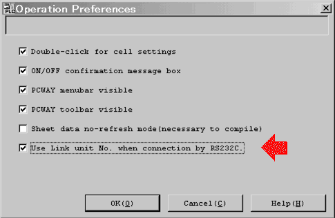
If you connect PCWAY to the port (TOOL port or COM port (only TOOL port for FP10S)) on CPU Unit, it is possible. (Not possible if connected to CCU.) When doing so add a checkmark to “Use Link unit No. when connection by RS232C?, as shown below. By making this setting you will be able to access PLCs existing on the same network. Please use station No. ?0? to access the local station.
How do I display the PLC calendar timer value in "YY/MM/DD" format on the spreadsheet?
This cannot be done unless you create an Excel Macro.
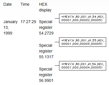
Use the calendar timer in special registers 9054 to 9056 to display the data in the following format on the Excel spreadsheet.
The date is January 13, 1999 and the time is 17:27:29
What does "merging cells" mean?
"Merging cells" refers to using an Excel function to join two cells together (say A1 and B1) in an Excel spreadsheet.
To join cells A1 and B1
1. Click the right mouse button with A1 and B1 selected.
2. Select the Alignment tab in the Format Cells window.
3. Select the "Merge Cells" check box, and click OK.
1. Click the right mouse button with A1 and B1 selected.
2. Select the Alignment tab in the Format Cells window.
3. Select the "Merge Cells" check box, and click OK.
The two cells A1 and B1 are now merged.
Use this to magnify the display. The merged cells can only contain the settings for one cell.
1. Test environment
Windows98
Excel97
PCWAY Ver. 2.102
Excel97
PCWAY Ver. 2.102
2. Functions with no problems
- Changing the contact character
- Register display
- Write processing to the above two
- Download function
- Register display
- Write processing to the above two
- Download function
3. Functions that cannot be used
- Copy and paste of merged cells
- Display of file data
Merged cells are unmerged when file data is displayed.
- Display of file data
Merged cells are unmerged when file data is displayed.
How do I display BCD?
To display and perform an operation in the same cell, use hexadecimal display for the cell data setting. However, in the case that there are fewer than four digits in the BCD display, (fewer than 8 digits for one or two word display), zeros are displayed in front of the other digits.
Example: PLC DT0 23 (HEX display) -> 0023 on the Excel spreadsheet
With the following method, it is possible to eliminate the leading zeros.
Example: PLC DT0 23(HEX display) -> 23 on the Excel spreadsheet
Setting method
1. Assuming 0023 is displays in the cell "A1" actually, you set the formula "VALUE(A1)" in the cell "A2" so that "A2" displays just '23' without '00'.
1. Assuming 0023 is displays in the cell "A1" actually, you set the formula "VALUE(A1)" in the cell "A2" so that "A2" displays just '23' without '00'.
2. Input the following operator into the cell in the Excel spreadsheet where you want to display BCD.
Example: If A1 is the cell position, input: =VALUE(A1)
What happens with PCWAY when the print macro is running, and a printer error (out of paper etc.) occurs?
There is no problem. Printer errors are handled by Windows, and not PCWAY or Excel. PCWAY and Excel will continue operating normally even if a printer error occurs.
Can I organize Excel macros on a book basis?
Yes you can, subject to the following conditions.
1. Open the Macro book at the back of the display book.
2. Use the PCWAY automatic macro start registration to add the book and set the macro names.
2. Use the PCWAY automatic macro start registration to add the book and set the macro names.
Example: If the macro book name is MACROTEST.XLS and the macro name is MACRO01.
Registered macro name: MACROTEST.XLS!MACRO01
Registered macro name: MACROTEST.XLS!MACRO01
If the display book and macro books are divided in this way, the macros for processing the version history book are also saved together, so it is easier to manage the data with Excel books.
When displaying file data, how can I switch rows and columns?
At the moment, the only way to do this is to first display the file data in a sheet, and then execute a macro on this data that switches rows and columns. Use "Register Auto Macro Launch" to set the macro to launch on, for example, a notification event set using "Register File Process",
1. Copy the macro of the blue part below into the module of the book that you are using. There is no need to edit it.
2. Operation methods of the macro below.
Example 1:
Switch the rows and columns in the range B2:D5 in Sheet 1, and paste them starting from B2 in Sheet2.
Call Application.Run("RowColumn_Change", "Sheet1", "B2:D5", "Sheet2", "B2")
Switch the rows and columns in the range B2:D5 in Sheet 1, and paste them starting from B2 in Sheet2.
Call Application.Run("RowColumn_Change", "Sheet1", "B2:D5", "Sheet2", "B2")
Example 2:
Switch the rows and columns in the range B2:D5 in the active sheet, and paste them starting from cell B7 in the active sheet.
Call Application.Run("RowColumn_Change", "", "B2:D5", "", "B7")
Note: this will not work if any of the destination cell positions are inside the range of the source cells.
Switch the rows and columns in the range B2:D5 in the active sheet, and paste them starting from cell B7 in the active sheet.
Call Application.Run("RowColumn_Change", "", "B2:D5", "", "B7")
Note: this will not work if any of the destination cell positions are inside the range of the source cells.
Example:
Switch the rows and columns of the file data is displayed in the range B2:D5 in Sheet1, and display from B7 in Sheet2.
Switch the rows and columns of the file data is displayed in the range B2:D5 in Sheet1, and display from B7 in Sheet2.
1) Copy the macro in the blue part below into the module of the book that you are using.
2) Create a macro.
Sub test()
'When copying between different sheets, the following three lines are required because the data in Sheet1 is not updated when Sheet2 becomes active. 'This macro "PCWAYsubSheetRefreshNoMessage" can only be used with Ver1.06 and later.
Sub test()
'When copying between different sheets, the following three lines are required because the data in Sheet1 is not updated when Sheet2 becomes active. 'This macro "PCWAYsubSheetRefreshNoMessage" can only be used with Ver1.06 and later.
If ActiveSheet.Name <> "Sheet1" Then
Call Application.Run("PCWAYsubSheetRefreshNoMessage", "Sheet1")
End If
Call Application.Run("PCWAYsubSheetRefreshNoMessage", "Sheet1")
End If
Call Application.Run("PCWAYsubRowColumnChange", "Sheet1", "B2:D5", "Sheet2", "B7")
End Sub
End Sub
3) Select the process checkbox of the "Register File Process" notification event, and register V0 as the event.
4) Select the "Register Auto Macro Launch" process checkbox, and register the trigger as V0, and the macro name as test.
End. Row to column switch process
--------------------------------------------------------
Parameter1 strFromSheet : Name of the source sheet. If "", it is the active sheet. Ex) "Sheet1"
Parameter2 strFromRange : Source switch range Ex) "B2:D10"
Parameter3 strToSheet : Name of the destination sheet. If "", it is the active sheet. Ex) "Sheet2"
Parameter4 strToCell : Start cell position in the destination sheet Ex) "B2"
Parameter2 strFromRange : Source switch range Ex) "B2:D10"
Parameter3 strToSheet : Name of the destination sheet. If "", it is the active sheet. Ex) "Sheet2"
Parameter4 strToCell : Start cell position in the destination sheet Ex) "B2"
Operation example 1:
Switch the rows and columns of the range B2:D5 in Sheet1, and paste from cell B2 in Sheet2
Call Application.Run("RowColumn_Change", "Sheet1", "B2:D5", "Sheet2", "B2")
Call Application.Run("RowColumn_Change", "Sheet1", "B2:D5", "Sheet2", "B2")
Operation example 2:
Switch the rows and columns of the range B2:D5 in the active sheet, and paste from cell B7 in the active sheet
Switch the rows and columns of the range B2:D5 in the active sheet, and paste from cell B7 in the active sheet
Call Application.Run("RowColumn_Change", "", "B2:D5", "", "B7")
Note: this will not work if any of the destination cell positions are inside the range of the source cells.
-----------------------------------------------------------
Sub PCWAYsubRowColumnChange(strFromSheet As String, strFromRange As
String, strToSheet As String, strToCell As String)
Dim strSheetname As String
If strFromSheet = "" Then
strSheetname = ActiveSheet.Name
Else
strSheetname = strFromSheet
End If
String, strToSheet As String, strToCell As String)
Dim strSheetname As String
If strFromSheet = "" Then
strSheetname = ActiveSheet.Name
Else
strSheetname = strFromSheet
End If
Worksheets(strSheetname).Range(strFromRange).Copy
If strToSheet = "" Then
strSheetname = ActiveSheet.Name
Else
strSheetname = strToSheet
End If
If strToSheet = "" Then
strSheetname = ActiveSheet.Name
Else
strSheetname = strToSheet
End If
Worksheets(strSheetname).Range(strToCell).PasteSpecial
Paste:=xlFormats, Operation:=xlNone, SkipBlanks _ :=False, Transpose:=True Worksheets(strSheetname).Range(strToCell).PasteSpecial Paste:=xlValues, Operation:=xlNone, SkipBlanks _ :=False, Transpose:=True
Application.CutCopyMode = False
End Sub
Paste:=xlFormats, Operation:=xlNone, SkipBlanks _ :=False, Transpose:=True Worksheets(strSheetname).Range(strToCell).PasteSpecial Paste:=xlValues, Operation:=xlNone, SkipBlanks _ :=False, Transpose:=True
Application.CutCopyMode = False
End Sub
When displaying the value in one cell in another cell, how do you display a blank as blank?
If, for example, you want to display the value in cell A1 in the cell B1, and set the formula in cell B1 to =A1, when the value in A1 is blank, "0" is displayed in cell B1.
To get around this, set the formula in B1 to =IF(ISBLANK(A1),"",A1).
This formula displays "" in B1 if cell A1 is blank, and the value in A1 if cell A1 is not blank.
When using PCWAY, the PC's clock data goes askew.
If PCWAY is launched while running virus scanning software, the clock will go askew, running faster.
The extent depends on the PC used, but if you frequently perform PCWAY file processing, in particular, the clock will delay about 10 seconds over a ten minute span.
When attempting to start up PCWAY, the message "Security unit not installed" is displayed and PCWAY does not start up.
An NEC PC9821 Series PC was used.
Since the serial port on this PC has a D-Sub 25 pin, installation may sometimes be incorrect. Unfortunately, the NEC PC9821 Series is not supported by PCWAY Ver. 2.3 and higher.
How do I display the contents of two registers in one cell?
To display the contents of, say, DT0 and DT1 in one cell, refer to the example given below.
*Example:
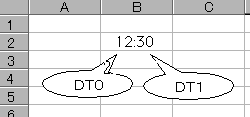
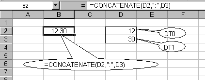
To display the PLC's hours and minutes, use a program to transfer the contents of DT9053 (hours/minutes) to DT0 and DT1.

Output deviates when the system register is initialized.
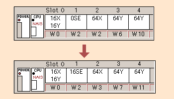
When there is a model change when using FPWIN GR, the content of the system register will be initialized and the I/O allocation is also initialized.
Although in the original I/O allocation setting, MEWNET-H was set to "0SE", it became "16SE" by being initialized when the model was changed.
This caused the addresses to shift one word back for all subsequent units.
This caused the addresses to shift one word back for all subsequent units.
"MEWNET manager run error" occurs and FPWIN GR does not launch after the OS on the PC is upgraded.
This phenomenon occurs when the OS is upgraded to Windows NT, Windows 2000 or Windows XP from Windows 9X onto which FPWIN GR was originally installed. This is because, in order to promote stability of applications, the folder/path that system files related to communications are stored are different for Win9X-lineage systems and WinNT-lineage systems.
If this phenomenon occurs, uninstall FPWIN GR and then reinstall it.
Communication works with the SDU connected to an external device (PC), but stops working after a different PC is connected to the CPU tool port and then removed. Later, when a different PC is connected to the tool port, the SDU is able to communicate, but it becomes unable to communicate when the tool port and the different PC are disconnected.
The pin layout on the RS232 cable is wired incorrectly.
For example, a straight cable is being used.
SDU device (PC)
2(SD) 2(RD)
3(RD) 3(SD)
5(CS) 4(GND)
7(GND) 7(RS)
2(SD) 2(RD)
3(RD) 3(SD)
5(CS) 4(GND)
7(GND) 7(RS)
With this wiring, communication is not normally possible because the GND of the SDU and the GND of the external device (PC) are not connected. However, if both the SDU and the GND of the external device (PC) have a similar potential, communication may be possible.
By removing and inserting the cable of a separate device in one of the ports of the PLC, the potential on the PLC side will change and communication will become disabled.
The solution is to rewire the connections correctly.
When I connect a Serial data unit (SDU here after) to an external device (PC) and attempt to communicate, the SDU can communicate when the PC is connected to the CPU tool port, but when the PC is disconnected, the SDU is not able to communicate.
The pin layout on the RS232 cable is wired incorrectly.
For example, a straight cable is being used.
SDU External device (PC)
2(SD) 2(RD)
3(RD) 3(SD)
5(CS) 5(GND)
7(GND) 7(RS)
2(SD) 2(RD)
3(RD) 3(SD)
5(CS) 5(GND)
7(GND) 7(RS)
With this wiring, communication is not possible because the GND of the SDU and the GND of the external device (PC) are not connected. However, by connecting a different PC to the CPU tool port, the GND in the PLC and FG become shared through the PC COM port connected to the tool port. Furthermore, since the SG of the PC connected to the SDU is connected to the FG in the PLC through that PC's FG, the FG of the communication cable and the FG of the SDU, it becomes shared with the SG in the PLC. As a result, communication becomes possible. The solution is to rewire the connections correctly.
Error 26 occurs when transmitting a MEWTOCOL command with station number 00 from a PC.
Valid, usable MEWTOCOL station numbers are EE or 01 to 64. If transmission is performed with any other station number, the station number setting error, error 26, is returned.
Overwrites cannot be performed during execution.
Although pixel writing during execution is possible on models with suffixes B or C in the part number, this is not possible on other models (because they are early versions, the suffix is A or a numeral).
Boolean ladder writing during execution is possible with all CPUs.
How to create two or more different systems?
1) Use Windows Explorer to create a working folder for the 2nd system
Example: Create the folder Testno2.
2) There is already a PLC folder in the folder that PCWAY was installed in, so copy all of the files in the PLC folder into the folder that you created in step(1).
3) Open the PCWAY operating environment settings, and change the working folder to the folder that you created in step (2).
Example: Change the setting to the Testno2 folder.
Example: Change the setting to the Testno2 folder.

4) All of the registered data is in the initiallized state, so perform the settings for the new system.
How do I temporarily turn off PCWAY in EXCEL?
When you install PCWAY, the PCWAY icons and menu items appear in Excel. If these get in the way when you are not using PCWAY, it is possible to temporarily turn them off and return to the original settings.
Method:
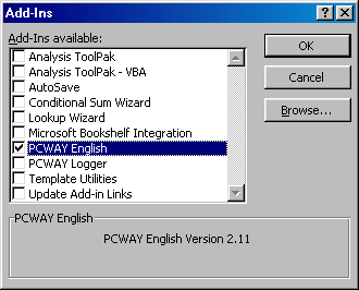
1) Select [Tools] - [Add-Ins] from the Excel menu bar.
2) Uncheck PCWAY in the Add-Ins window.
1) Select [Tools] - [Add-Ins] from the Excel menu bar.
2) Uncheck PCWAY in the Add-Ins window.

3) Restart Excel. The items related to PCWAY will not be displayed.
When the target speed only is raised at the same target position, it moves 3 times more than it should.
When normal When abnormal
Startup speed 100 100
Target speed 1000 1000
Deceleration time 10 10
Target value 325 325
Move result 325 975
With a user program, the E point startup signal turned on at 100 msec, but with the data on the right hand side, above, one movement finished in 44 msec. Since the startup signal was still on even after the movement was finished, further movement occurred.
Even though I carried out remote programming using W2 mode on the FP2 Multi-wire link unit, the "W2" item does not show up as a choice for network communication station setting.
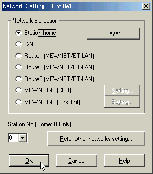
The communication station setting appear on screen following the pattern shown below: on the 3rd to 5th level down, the "MEWNET" of "Route * (MEWNET/ET-LAN)" stands for MEWNET-P/ MEWNET-W/ MEWNET-W2.
Operation is fine when using only a master backplane, but when an expansion backplane is connected the LEDs of the power supply unit and CPU unit on both the master and expansion sides turn off.
This type of phenomenon occurs when power is not correctly supplied to the power supply unit on the expansion side. Also, this type of phenomenon occurs when the unit's total current consumption (5V) on the expansion side exceeds the capacity of the power supply unit on the expansion side.
What is the operating environment for FPWIN GR?
OS | Windows 95/98/NT (Ver. 4.0 or later)/2000/XP Home/XP Pro
Required hard disk capacity | 30MB or more
Recommended CPU | 100MHz Pentium or faster
Recommended installed memory | 32MB or more
Recommended monitor | 800 x 600 pixels or more
Recommended color | High Color(16-bit) or higher
The power turned on, but the LEDs of the power supply unit and the CPU did not illuminate.
This type of phenomenon occurs when the unit's total current consumption (5V) exceeds the capacity of the power supply unit.
Are there any functions present in NPST-GR but not FPWIN GR?
Refer to the following list
- The Merge Registration and loading functions.
Use the Copy and Paste functions in Windows.
- Verifications cannot be carried out targeting files.
The file to be verified must first be loaded, and then verified.
Use the Copy and Paste functions in Windows.
- Verifications cannot be carried out targeting files.
The file to be verified must first be loaded, and then verified.
The internal relay turns itself on when the power is turned off and on.
When a battery is not installed, this phenomenon occurs when system register No. 7 (start number of the internal relay holding area) is set to a value lower than the initial value 90. Use in this way causes an attempt to back up internal relay R using the battery, but since the battery is not installed the status of the area set for holding is not definite. The same thing can be said for the timer counter elapsed value of system register No. 6 and the value of data register No.8.
If a battery is not installed, please leave this setting at the initial value. (Areas subsequent to the area set with the initial value are backed up in the EEP-ROM area, so there is no possibility of values becoming indeterminate.)
Can NPST-GR read files created using FPWIN GR?
To enable a program created using FPWIN-GR to be read by NPST-GR, export it using the Export function. However, the comments cannot be read.
*Reference information
If programs and comments created using FPWIN GR are downloaded to a PLC with comment memory, it is not possible for NPST-GR to read out the comments. It can, however, read the program.
If programs and comments created using FPWIN GR are downloaded to a PLC with comment memory, it is not possible for NPST-GR to read out the comments. It can, however, read the program.
Can FPWIN GR read files created using NPST-GR?
It can read files created with NPST-GR Ver. 3 or Ver. 4 (including I/O comments, Remarks, and Block comments).
If operation is stopped by the JOB stop signal during positioning operation (JOG operation), does operation decelerate to a stop or stop immediately?
It decelerates to a stop according to the acceleration/deceleration of positioning data.
Is it possible to return to the home position using just the home position sensor?
Yes. By setting bit 5 of the control code to on, you can make it as though the near home sensor was on from the outset. If you perform a return to near home in this state, the operation will take place a low speed.
I set the parameters and data, but the next day they were gone (E Type). Why?
In the case of the E Type, you have to write the settings to the EEPROM. Write the data using "Expansion" + "0" with the Teaching Unit, or use a program to write the data.
What are the benefits of using data No. 401 to 410 of the Positioning Unit (F Type)?
If there are 10 or fewer items of positioning data, using No. 401 to 410 allows you to avoid having to perform a write transfer. This affords the following benefits:
- Faster response time when you want to perform immediate positioning using data loaded from the outside.
- Shorter programs because there is no need for a write transfer program.
- Shorter programs because there is no need for a write transfer program.
Is JOG operation possible when an overrun switch has been on?
Yes. However, movement is either clockwise or counter-clockwise.
Does pulse output stop when an overrun switch is on during JOG operation?<
12th Dec 2022
Recent Posts
-
Absolute Encoders — Facts and Misconceptions
Ray Marquiss 11th Sep 2023There are two parts of motion control systems often overlooked or misunderstood; encoders for … -
What is a Compound Pressure Gauge and When to Use One?
Valin 12th Dec 2022What is a Compound Pressure Gauge and When to Use One? I just got off the phone with a … -
What is an Encoder?
Encoder Products Company 12th Dec 2022If you search the definition of an encoder, you will get a vast and confusing array of responses. …

