Frequently Asked Questions for Panasonic Programmable Displays
Panasonic 12th Dec 2022
Can the screen data of GT10 be used for GT11 as is?
If any changes are required, what procedures should I follow?
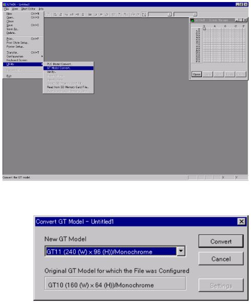
You can use the screen data of GT10 for GT11 by converting the data as follows:
Go to “File” of the GTWIN menu bar > Utility > GT model convert…, select “GT11(240(W)x96(H)Monochrome” in the “Convert to” section, and execute the conversion.
Since the number of dots will not be changed by the conversion, the data will look smaller. Change the character size if necessary.
[Notes for the cases where the data parts are displayed in ASCII format]
The data storage position and display position for ASCII format of data parts with an odd number of digits of GT10 are different from those of GT11.
Therefore, switch to an even number of data digits to match the data storage and display positions of GT10 with those of GT11.
(Example: Change the three-digit display to a four-digit display.)
There are no problems in displays in DEC or BCD format.
More info below:
You can use the screen data of GT10 for GT11 by converting the data as follows:
Go to "File" of the GTWIN menu bar > Utility > GT model convert, select "GT11(240(W)x96(H)Monochrome" in the "Convert to" section, and execute the conversion.
Since the number of dots will not be changed by the conversion, the data will look smaller. Change the character size if necessary. (Notes for the cases where the data parts are displayed in ASCIIformat) The data storage position and display position for ASCII format of data parts with an odd number of digits of GT10 are different from those of GT11. Therefore, switch to an even number of data digits to match the data storage and display positions of GT10 with those of GT11. (Example: Change the three-digit display to a four-digit display.)
There are no problems in displays in DEC or BCD format.
There are no problems in displays in DEC or BCD format.
Error 61 appears in the screen of the display device connected to the FP Series.
Almost all error numbers of the programmable display are obtained as error responses issued from the PLC. The FP Series error 61 (data error) means that there is a mistake in the contact number or data number designation.
Please verify that the memory number used by the programmable display screen or part is within the PLC memory number range.
The message "Time out error" is displayed when the GT series through mode is used, the PC (FPWIN GR) and PLC are connected, and an overwrite is done during execution.
Sometimes time is required to overwrite during execution depending on the PLC type and program size. This phenomenon occurs when the response from the PLC takes longer than the wait time setting of the GT.
From the GTWIN menu bar go to 'File' - 'Configuration' - 'GT Configuration' - 'Communication Parameters' tab and click the 'Setup' of Handle Communication Error and lengthen the 'waiting' setting.
Power was turned on at the same time as the PLC and at first error FF was displayed and then it took about 20 seconds before transmission started.
When the PLC and GT transmission speeds do not match, this phenomenon occurs because the GT automatically switches the speed and finds a suitable setting. Please set matching communication speeds for both the PLC and GT.
After creating a GT10 screen and then converting to GT30 with the GT type conversion feature, the message "There are invalid switches. Continue?" appears.
When placing a switch part using GT Series you must surround the touch switch with at least one space. With GT10 the size should be 16 dots. With GT30 it should be 20 dots. The size (number of dots) of switch parts made on the base screen of the GT10 will not change when converted over to the GT30.
If you placed small switches using GT10 and then converted over to the GT30 the size may turn out smaller than the GT30's smallest size. This error message will appear when this happens.
In this situation, please enlarge the switch part size.
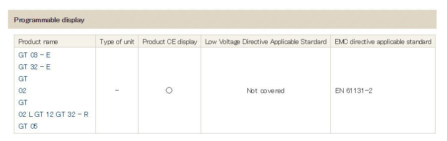
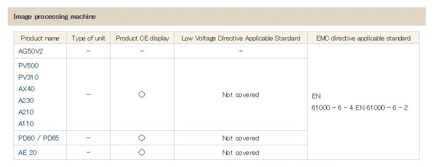
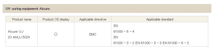
To which foreign standards do GT series touch panels conform?
Please check below for the foreign standard acquisition situation of the GT series:
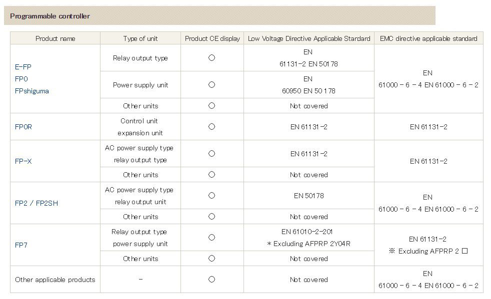
Note: For both models, please confirm the target part number. Handling of accessories such as cables and expansion memory : CE marking is not displayed on the product because it is out of the applicable standards for cables and expansion memories individually. It is set with the PLC body and conforms to the applicable directive on the left.
Note: For both models, please confirm the target part number.
Note: For both models, please confirm the target part number.
Note: For both models, please confirm the target part number.
Can I download the GT30 English manual?
All of our manuals are located at the following URL: https://www.valinonline.com/documents/panasonic/manuals
I need to display overlap data screens by using PLC devices (contacts or data register bits). What’s the best way?
Use the ON Macro and OFF macro, and you can display data when needed.
I need to display and delete data indications on the overlap screens using switch parts. How do I do this?
Set the switch parts to the overlap display to easily display the overlap screens.
When pressing DA0 on the keyboard, data entry is possible. However, I need a setting that activates DA0 entry when R150 is turned on by pressing SW0.
SW0 settings: Momentary (R150), Do ON/OFF, Switch held down. DA0 settings: Activation condition, ON, Reference device = R150. All are attached on the same screen.
The R150 contact must be kept in ON state to activate DA0 entry on condition that R150 is turned on.
Therefore, DA0 entry cannot be activated with the momentary contact, which can keep R150 on only for a moment
To solve this, when setting SW0, set R150 to “Bit Set”.
In addition, to reset R150 after data entry, set an output trigger to R151 in the DA0 entry settings, and reset R150 in the PLC’s program.
Refer to the attached sample screens and program files.
When displaying a message using a message part, what does “Reference device: DT100-0” mean? And how do I display 17 or more message patterns?
It means that the value in the 0th digit of DT100 is referred to. DT100 comprises 16 bits. They are divided by four bits, and the group of the lower four bits is the 0th digit. The target message can be displayed by entering hexadecimal values from H0 to HF for this digit.
Use a message part in the custom parts library to display 17 or move message patterns. If you set the switch method to “Direct”, GT30 can display up to 256 message patterns by entering values from K0 to K255 in DT100. (GT10 can display up to 50 patterns by entering K0 to K49.)
When operating GT10, rainbow-color dots are seen on the surface. How can I solve this?
This is an optical phenomenon called Newton’s ring, which is caused by the adherence of a thin film.
This phenomenon is unavoidable to a greater or lesser degree for products using sheet material. When the backlight is turned on, it becomes less noticeable.
Can I display or erase the switches on the screen?
Use the custom switch parts. To turn off the display, don’t create screen data(Transparent state) for the OFF mode, and set the valid condition so that the switch parts will not operate in OFF mode.
When I transferred screen data created by using a TrueType font to GT10, the screen flashed and couldn’t be operated. How do I restore it?
If screen data created with a TrueType font is transferred to GT10 Ver. 1, then the screen flashes, making the operation impossible. In this case, turn on DIP switches No. 2, 3, and 4 at the rear of the GT10 unit, and reset the power supply. This step will reset the unit to factory defaults. After the unit is restored, return the DIP switches and then power on again.
What’s the substitute product for AIP1042 (IOPM01TL)?
Substitute: AIGT1000B (GT10).
Compatibility:
Dimensions: The front face dimensions are the same, but the panel cut dimension (height) is 1 mm larger.
Functions: Not equipped with function switches. Operated by touch switches.
Screen creation: You need separate screen creation software. The screen data is not compatible with that created for the previous model.
PLC: Connection with FP series (e.g. FP1, FP-M, FP0) is possible. You don’t need to revise the PLC program if you set the basic communication area in Earlier Model Compatibility Mode. If you set it in GT mode, you also need to change the PLC program.
Connection cable: You need cables for both screen creation and PLC connection. The cable for screen creation comes with GTWIN software. For PLC connection, purchase AIGT8192 (for the TOOL port of FP-M, FP0, etc.) or AIP81842 (for the COM port of FP1, FP2, etc.).
How do I connect GT30 to FPΣ?
Connect the COM port of GT30 and the TOOL port of FPΣ using an AIGT8192 cable. Use the TOOL port of GT30 for screen creation. The “Through” function allows you to operate FPΣ programming and monitor communications through the TOOL port of GT30.
The following error message appears when I try to open a saved GT30 screen data file, preventing me from opening it.
“The filecannot be opened,because the working file could not be generated. Change the working drive at [Drive Setting] in [GTWIN Configuration].”
How do I solve this?
This error message appears when the file names with extension “.IOP”, “.HSY”, and “.WDF” are not identical to one another. Correct the file names to an identical one. In addition, when e-mailing the files, make sure to compress them into an archive file. Otherwise, some e-mail software will automatically change the file names.
Is it possible to create GT10 screens with different language fonts mixed (Hangul, Chinese, English, and Japanese)?
It is possible with either the Japanese or English version of GTWIN more than Ver. 2.21 if it runs on Windows XP. (It is also possible on Windows 2000, but operation is easier on XP).
The data parts I created are not displayed on the GT30 screens, and only characters are displayed. PLC is not connected.
Data parts are not displayed without a PLC connected because the DT value is not identified. Connect a PLC (even if it has no programs or is in PROG mode).
GT30 made a general-purpose serial communication setup is connected to the COM port of FP2. However, they don’t communicate. There are no problems in either the cable connection or electric continuity.
If the target PLC of GT30 is set to “general-purpose serial communication”,communications with FP2 are impossible. In this case, go to File > Utility > Convert PLC Model, and select Matsushita MEWNET-FP Series.
How do I paste the GT10 screen data into Excel or Word?
Go to "Edit" in the menu bar, and select "Copy Bitmap of Base Screen" to copy the screen data to the clipboard in bmp format. Read and paste the data into Excel or Word.
When connecting GT30 touch panel to the TOOL port of FP10SH, how do I achieve a communication speed of 115.2 kbps? The DIP switch for setting the communication speed of the CPU unit can only switch between 19,200 bps and 9,600 bps.
Set the communication speed setting DIP switch of the FP10SH CPU unit to 19,200 bps (turn OFF No. 1). Then open FPWIN GR programming software, go to Option > PLC Configuration > COM Port > No. 414 TOOL Port Baudrate, and select 115,200 bps. Upload this setting to FP10SH to complete.
When connecting GT30 to FP0, error 61 is indicated. Why?
The error occurs when you specify a device that cannot be used by FP0 (e.g. contacts and data registers) as a screen data part of GT30. Check the device setting details of the registered parts and change them to devices that can be used by FP0.
GT30: Can I switch screens by using both the function switch and programmable controller?
You can switch the screens using the function switch by directly designating a screen number regardless of the controller status. You can also switch the screens from the controller by writing the screen number data in DT0. However, if you use both methods, there will be a difference between the screen switching data in DT0 and the currently displayed screen data in DT2, and screen switching by the controller may be impossible. In such cases, set the screen switching data in DT0, and then set and reset the forced screen switching flag (internal relay RE).
I’m using GTWIN screen creation software for the GT series. When I arranged long and thin switches vertically and then saved the screen data, the message “An invalid switch part exists.” appeared.
Is there a standard rule for switch arrangement? And how do I arrange as many switches as possible?
When a switch part doesn't fit within the touch switch area, or is smaller than the touch switch size, the message appears. The solution is to set the reference grid pitch to the standard and enable the snap function. With this setting, even when a switch part is moved, the four corners of the touch switch will automatically fit within the switch part.
GT30 cannot communicate with a notebook PC. (FP2 can communicate with it. Both FP2 and GT30 can communicate with a desktop PC.)
Set the Transmit Buffer slider to the lowest position in the advanced settings for the COM port of your PC. If this does not solve the problem, please purchase a commercially available USB-RS232C converter and connect it to the USB port.
Is GT21C connectable with the sequencer FX3U of Mitsubishi?
It is possible. However, the device which can be used serves as the same range as FX2N. (It is the range which can be set up by GTWIN.)
Guidance is not displayed although set up for "Display text" by the item of a guidance call with the alarm list parts of GT30. What should I do?
Please stick the function switch (FSW) for displaying guidance on a screen. A setup of this switch checks Operation Mode to "To Operate Alarm Parts", and Alarm Format is made "Display Guidance".
Does GT10 conform to the UL standards? If yes, what is the certificate number?
GT10 is certified by UL (File: E96300 Project: 01SC04197). GT30 is also certified (File: E96300 Project: 01SC04383).
Normally, up to 16 message patterns can be registered into a standard message parts. How can I register 20 patterns?
Select the custom message parts and set the replacement tag method to “Direct”. You can register 50 patterns for GT10 and 256 for GT30. Each part must be created by using the drawing function.
When setting the time of GT10 and then doing a power-off reset, the date changes to 2001-8-23. How do I solve this?
Turn ON DIP switch 1 on the rear. Otherwise, the SRAM backup will not be executed.
GT30 screen switching by PLC program [F0 MV, H10, DT1] doesn’t work well. Why?
Change “DT1” in [F0 MV, H10, DT1] to “DT0”. Switching is also impossible when the screen data specified by the PLC (DT0) does not match the currently displayed screen data (DT2). In such a case, turn ON the forced screen switching flag RE, and the screen will be forcibly switched.
Since both FP2 and GT30 have been embedded, I cannot connect a cable to the TOOL port. How do I solve this problem?
You can use the “THROUGH” function of GT30. Connect FP2 and GT30 with an AIGT8192 cable. Connect the AFC8532 cable to the TOOL port of GT30 and locate the connector on the panel. Connect a PC to the AFC8532 cable with an AFC8503 cable. With this configuration, you can edit both the GT30 screen data and FP2 ladder programs.
What is the difference between the keyboard part and keyboard screen for entry of data parts?
When attaching a data part, enabling “Data entry in the attribute editing screen”, and then choosing a corresponding keyboard, designate the number of a keyboard part attached on the same base screen if any. Another possible method is to designate a keyboard screen pre-edited using the keyboard screen editing function in the menu bar without attaching the keyboard part on the base screen. In the latter method, you can prepare the screen data separately from the base screen. Therefore, the latter method is useful if you need to enter a large amount of data.
The image designs of standard parts SW1 and FSW1 are the same. How do I distinguish between them on the screen?
You can distinguish between them by ticking Part No. and Part Attribute Indication in Indication on the menu bar. But the indication is displayed on the base screen on GTWIN only. It is not displayed on the GT series screens. If you need to distinguish between the designs on the GT series screens, set the characters for the parts.
How many alarm records can GT30 store? When the memory is filled to capacity, what happens to newly entered data?
Up to 2,800 data records can be stored. After the memory is filled to capacity, old data is erased and then the newly entered data is stored.
Why does error E61 appear on the touch panel section of the screen?
The error appears when reference data of a switch or data part used on the screen does not exist in the connected PLC.
Check the touch panel settings.
Although I set a clock IC in FP2, the calendar setting was not automatically downloaded into GV. Why?
The calendar data is not downloaded to GV by only setting a clock IC in FP2 because the calendar data has not yet been set correctly. Correctly set the calendar on the FP2 unit first. Then connect GV to the unit, and the GV will automatically read the data and complete the calendar setting. The GV automatically reads the calendar data from the PLC when powered on and when the date changes.
Please explain the general-purpose communications protocol for GT series.
There are two types: Command response and duplex communications. For details, refer to the GT series General-purpose Serial Communication Manual in PDF format available at:
When created screen data is transferred to GT10, only the target screen is changed, and the other old screens remain. Does this also occur with FP0?
If old data remains in the GT10 unit, only the target screen is overwritten with the newly created screen, and the other old screen data remains. To replace all screens with new ones, go to the system menu of the GT10 unit, clear the FROM area to delete all screen data before transferring the new data. GTWIN Ver. 2.2 or later allows you to choose the option of “Transfer after screen data deletion”. Check this option, and the FROM area will be automatically cleared before the new screen data is transferred. With regard to FP0, FPWIN deletes the old program data before writing new one. Therefore, there’s no need to carry out the deletion operation.
How do I sound the buzzers? Can I change the tone?
There is a buzzer relay in the basic communication area. When the word-unit internal relay is WR0, the bit-unit internal relay is RF. Turn ON this relay from the PLC. Since only one tone is available, it is recommended that you differentiate the sound by setting different flicker times using the flicker relays from R901A to R901D.
(The highest possible ON/OFF frequency is 100 ms.)
Why does a battery mark appear in the lower right corner of the screen?
The battery exhaustion mark appears because the battery insulating sheet is not removed. Open the back cover and remove the insulating sheet from the backup battery.
Why does “The data size is too large to write in the file.” appear when many parts are attached to the screen?
The size of data that can be attached to one GT10 screen is limited to 12Kbytes. Check the data size with the “used memory of the base screen” on the menu bar.
How do I reduce the size of the characters for the switch parts of GT10?
The font size is fixed by default. Change the font to a TrueType font on the switch attribute editing screen. This will enable you to change the character size by choosing a point size.
What is the latest part number for the GTWIN screen creation software?
The English version is AIGT8001V2 , and the upgrade version is AIGT8001V2R.
Check our software page for updated installers: https://www.valinonline.com/documents/panasonic/software
When creating GT10 screen data using GTWIN, if I change part data on a screen, can the change be automatically applied to data for the same part on all other screens?
Unfortunately, it is impossible. Change the data on a screen-by-screen basis.
I use both the instruction from PLC (FP0) and the function switches of GT11 to switch the screens. However, the second instruction from the PLC does not work.
When both the function switch and the PLC are used for screen switching, it causes mismatch between the screen data specified by the PLC (DT0) and the currently displayed screen data (DT2), and it may become impossible to switch the screens by PLC. The following is a sample program to solve this problem. The key point is to SET and RESET the forced screen switching flag RE. Write this program just before the END instruction.
(Example) Program for switching between screens 0 and 1
For FP-MC16T, FP1C14, and C16, use instruction F60.
For FP-MC16T, FP1C14, and C16, use instruction F60.
What size is the display of GV52S?
158.4 mm high x 211.2 mm wide
If a GT30C used for general-purpose communications is powered on while holding down a touch switch, does it function as switch? Can I set it by pressing two touch switches in combination?
When powering on while holding a touch switch down, it functions as a switch if the communication speed and format have been appropriately set. Pressing two switches in combination is not possible as per factory settings. It can be enabled by changing the settings on GTWIN (GT configuration - Settings - Enable two-switch pressing) and importing the settings to GT30C.
GV62 is connected to FP2. When GV62 displays a specific screen, communication error 61 occurs and it hangs. Why?
This error occurs when the GV62 tries to display a relay or other device that is not used on the FP2 side. Check the relay number.
When connecting FP0 to GT30 and conducting a rewriting operation in RUN mode using the “through” function, “NOT SUPPORTED” error occurs. This does not occur when using FP2. Why?
Change the connection with the COM port to TOOL port. COM ports of FP0 and other small-size PLCs do not support online rewriting.
I need to connect three GV52 units and one GT11 unit to the PLC. Which model is recommended?
FP2SH is recommended. (Use CCU.) Up to four groups of communication ports can be used. (Connection to FP2 is possible. However, since it has only two groups of communication ports, simultaneous communications result in an error.)
12th Dec 2022