Inductive Proximity Switch as Encoder
Contrinex 12th Dec 2022
Why Inductive?
Inductive proximity switches are enormously popular with end-users. They are
• robust
• good value for money
• insensitive to dirt
• standardized
and, as a result, simple to install.
Inductive Proximity Switches as Encoders
Today, encoders are mature products, and are available in a variety of designs. However, compared to inductive proximity switches, they are significantly more expensive. In addition, they have rotating axes, and consequently require a certain care during assembly. Finally, encoders are often far too efficient for the requirements of the job to be done.
Substituting the encoder with an inductive proximity switch, which detects already present mechanical parts, such as a gear wheel, is a frequently used alternative. Where no suitable gear wheel is available, an additional one (or any suitably fabricated toothed disk) can be specially added. If need be, extra holes can be drilled in a co-rotating part, or a shaft with milled-on grooves, or equipped with spigots, can be used. In this way, a cheap, simple, and reliable substitute encoder is obtained. However, in practice, this solution often leads to difficulties, and the performance obtained is disappointing. This may be overcome by following the tips for optimum assembly given below.
Design for Optimum Resolution and Switching Frequency
It should be stated at the outset that the values obtained from encoders with respect to resolution and switching frequency cannot be matched by a long way. However, the obtainable results are greatly influenced by the correct choices of proximity switch and gear wheel, which therefore require great attention.
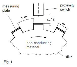
The test method for the switching frequency of inductive proximity switches according to IEC 60947-5-2/EN 60947-5-2
(Fig.1) gives a good clue to achieving optimum results. In effect, this method, characterized by a tooth/gap mechanical ratio of 1:2, and an operating distance s set to half the nominal operating distance sn, corresponds approximately to the optimum conditions with respect to resolution and switching frequency.
Choice of Proximity Switch
On physical grounds, the maximum switching frequency of an inductive proximity switch is approximately inversely proportional to its outside diameter. The smallest possible diameter proximity switch is therefore the most suitable for achieving high switching frequency. However, particularly when dimensions are small, the physically possible upper limit is not fully utilized, because the manufacturers analyzing circuit has not been optimized for the switching frequency. This is even more the case since the CE mark has been required: switching frequency and EMC resistance are opposite quantities. There are considerable differences from manufacturer to manufacturer, which should be taken into account. The best results (close to the physical limits) are obtained with NAMUR proximity switches (0IN/EN 19234), as long as they are built-in discretely (no IC). Here also, appropriate clarification from the manufacturer is worthwhile.
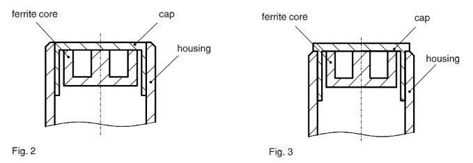
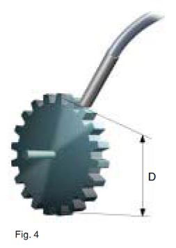
The above is naturally also valid for the resolution: the smaller the proximity switch, the better. Nevertheless, there are differences here also. Variant 1 (Fig.2), with the ferrite core recessed with respect to the housing, gives better resolution than variant 2 (Fig.3), as a result of better field bundling. However, for the manufacturer, variant 2 is simpler, since the pre-damping through the housing is lower, and consequently the operating distance temperature stability requirements are easier to maintain. Whether the instrument is of the type variant 1 or variant 2 can easily be determined visually, but, as a rule, not from the information given in the catalog.
| Size | Module M (1) | Module M (2) |
|---|---|---|
| Ø 3 | 1.5 | 1.25 |
| M4 | 1.5 | 1.25 |
| D4 | 3 | 2 |
| M5 | 3 | 2 |
| D6,5 | 4 | 3 |
| M8 | 4 | 3 |
(2) under favorable conditions
| Size | D1 | B |
|---|---|---|
| Ø 3 | 3 | 1.5 |
| M4 | 3 | 1.5 |
| D4 | 4.5 | 2 |
| M5 | 4.5 | 2 |
| D6,5 | 7 | 3.5 |
| M8 | 7 | 3.5 |
B inter-hole spacing
Dimensioning the Gear Wheel or Perforated Disk
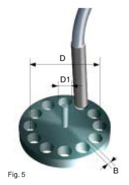
The geometry of a standard gear wheel (Fig.4) closely approaches the ideal form (see above under switching frequency). The fact that the tooth flanks are not at right angles to the tooth surfaces makes no significant difference. However, the size of the proximity switch must be properly suited to the gear wheel module (table 1). For a perforated disk (Fig.5), the recommendations given in table 2 are applicable.
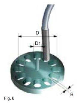
Better results can be obtained with elongated holes (longitudinal axis) (Fig.6). Other geometric variations must be optimized by trials.
Optimum Operating Distance
The optimum operating distance for the "safe solution", according to table 1, is 0.5 x sn. For an "acceptable solution under favorable conditions", it is approximately 0.6 x sn, but during assembly it must be individually adjusted by means of a signal check, using an oscillograph.
Contrary to the recommendations, shorter operating distances lead to lower switching frequencies, lower resolutions, but better operating security. Longer operating distances give lower operating frequencies, higher resolutions, and lower operating security. It should be pointed out here that poor results are often caused by operating distances being too short.
Maximum Rotational Speed
By adhering to the preceding instructions, it can be assumed that the manufacturer's stated maximum switching frequency will be reached. The following is therefore valid for the maximum rotational speed
N = (60 * fmax) / Z (rpm) (1)
or with Z teeth, or holes
Z = D / M (2)
for the gear wheel, or
Z = (π * D) / D1 + B (3)
for the perforated disk. At maximum rotational speed N
N = (60 * fmax * M) / D (rpm) (4)
for the gear wheel, or
N = (60 * fmax * (D1 + B)) / π * D (rpm) (5)
for the perforated disk, where
N = maximum rotational speed
Z = number of teeth or holes
fmax = maximum switching frequency of the proximity switch
D = gear wheel or perforated disk diameter (pitch circle)
M = gear wheel module
D1 = hole diameter
B = inter-hole spacing
Resolution
In the case of a gear wheel, the maximum resolution A is fixed by the module, and is calculated by
A = (360 * M) / D (degrees) (6)
for the gear wheel. For a perforated disk, it is
A = (360 * (D1 + B)) / π * D (degrees) (7)
Practical Examples
Example 1
Given a gear wheel of maximum outside diameter 30mm, find the best possible resolution.
The smallest possible module for the "safe solution" (table 1) is M = 1.5, giving a corresponding proximity switch size of D3/M4. According to (6), the resolution is
A = (360 * 1.5) / 30 (degrees)
resulting in
A = 18^0
The maximum switching frequency of the chosen 3-wire proximity switch is 5 kHz. The maximum rotational speed according to (4) is therefore
N = (60 * fmax * M) / D (rpm)
giving the result
Nmax = 15'000 rpm
Example 2
Given a perforated disk with a pitch circle diameter of 100mm, find the best resolution that can be obtained with a maximum rotational speed of 3000 rpm, together with the most suitable proximity switch.
According to (7), the resolution will be
A = (360 * (D1 + B)) / π * 0 (degrees)
In principle, the best resolution can be obtained with the smallest device, i.e. sizes D3/M4. The corresponding values are:
D1 = 3
B = 1.5
From this
A = (360 * (3 + 1.5)) / π * 100 (degrees)
with the result
A = 5.2 degrees
The switching frequency at 3000 rpm is calculated by reformulating (5) to
fmax = (π * D * N) / (60 * (D1 + B)) (Hz)
i.e.
fmax = (π * 100 * 3000) / 60 * (3 + 1.5) (Hz)
resulting in
fmax = 3490 Hz
The maximum switching frequency of 5 kHz for the Ø 3 / M4 device will therefore be respected.
12th Dec 2022